2-37
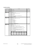
Pin Name
I/O
Description
Option
Port 7
• 4-bit I/O port
• I/O specifiable in 1-bit units
• Pull-up resistor can be turned on and off in 1-bit units
• Shared pins
P70 : INT0 input/HOLD reset input/timer 0L capture input/watchdog timer output
P71 : INT1 input/HOLD reset input/timer 0H capture input
P72 : INT2 input/HOLD reset input/timer 0 event input/timer 0L capture input/
high speed clock counter input
P73 : INT3 input (with noise filter)/timer 0 event input/timer 0H capture input
AD converter input port: AN8 (P70), AN9 (P71)
• Interrupt acknowledge type
Rising
Falling
Rising/
Falling
H level
L level
INT0
enable
enable
disable
enable
enable
INT1
enable
enable
disable
enable
enable
INT2
enable
enable
enable
disable
disable
INT3
enable
enable
enable
disable
disable
P70 to P73
I/O
No
Port 8
P80 to P86
I/O
• 7-bit I/O port
• I/O specifiable in 1-bit units
• Shared pins
AD converter input port : AN0 (P80) to AN6 (P86)
No
PWM2
PWM3
I/O
• PWM2 and PWM3 output ports
• General-purpose I/O available
No
Port 3
P30 to P37
I/O
• 8-bit I/O port
• I/O specifiable in 1-bit units
• Pull-up resistor can be turned on and off in 1-bit units
• Pin functions
P32: UART1 transmit
P33: UART1 receive
P34: UART2 transmit
P35: UART2 receive
Yes
Port C
PC0 to PC7
I/O
• 8-bit I/O port
• I/O specifiable in 1-bit units
• Pull-up resistor can be turned on and off in 1-bit units
• Pin functions
PC5 to PC7: On-chip Debugger
Yes
RES
Input
Reset pin
No
XT1
Input
• 32.768kHz crystal oscillator input pin
• Shared pins
General-purpose input port
AD converter input port : AN10
Must be connected to VDD1 if not to be used.
No
XT2
I/O
• 32.768kHz crystal oscillator output pin
• Shared pins
General-purpose I/O port
AD converter input port : AN11
Must be set for oscillation and kept open if not to be used.
No
CF1
Input
Ceramic resonator input pin
No
CF2
Output
Ceramic resonator output pin
No
Summary of Contents for SH33SD-S
Page 25: ...2 16 4 SLED CONTROL RELATED SIGNAL NO DISC CONDITION FIG 4 1 1 2 3 4 1 2 3 4 ...
Page 27: ...2 18 FIG 7 2 DVD 7 DISC TYPE JUDGEMENT WAVEFORMS FIG 7 1 DVD 1 2 3 IC501 IC501 1 2 3 1 2 3 ...
Page 28: ...2 19 FIG 7 4 CD FIG 7 3 CD 1 2 3 IC501 IC501 1 2 3 1 2 3 ...
Page 29: ...2 20 FIG 8 2 CD 8 FOCUS ON WAVEFORMS FIG 8 1 DVD 1 2 3 1 2 3 4 4 1 2 4 3 IC501 ...
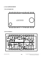
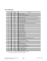
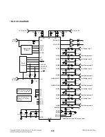
Page 41: ...2 32 2 IC401 MOTOR DRIVER PIN CONFIGURATION BLOCK DIAGRAM ...
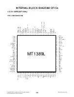
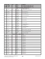
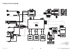
Page 42: ...2 33 1 IC501 MPEG MT1389L PIN DESCRIPTION ...
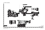
Page 66: ...2 69 2 70 PRINTED CIRCUIT BOARD DIAGRAMS 1 MAIN P C BOARD DIAGRAM TOP VIEW ...
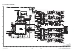
Page 67: ...2 71 2 72 MAIN P C BOARD DIAGRAM BOTTOM VIEW ...
Page 74: ...2 PASSIVE SUBWOOFER SH33SD W 950 A90 951 953 956 954 952 955 WIRE90 3 7 ...
Page 75: ......


