


Installation
5
Connection
Precautions
•
Be sure to switch off the unit before installation and connection.
•
The installation should be made by qualified service personnel or
system installers.
•
Do not expose the power and connection cables to moisture, which
may cause damage to the unit.
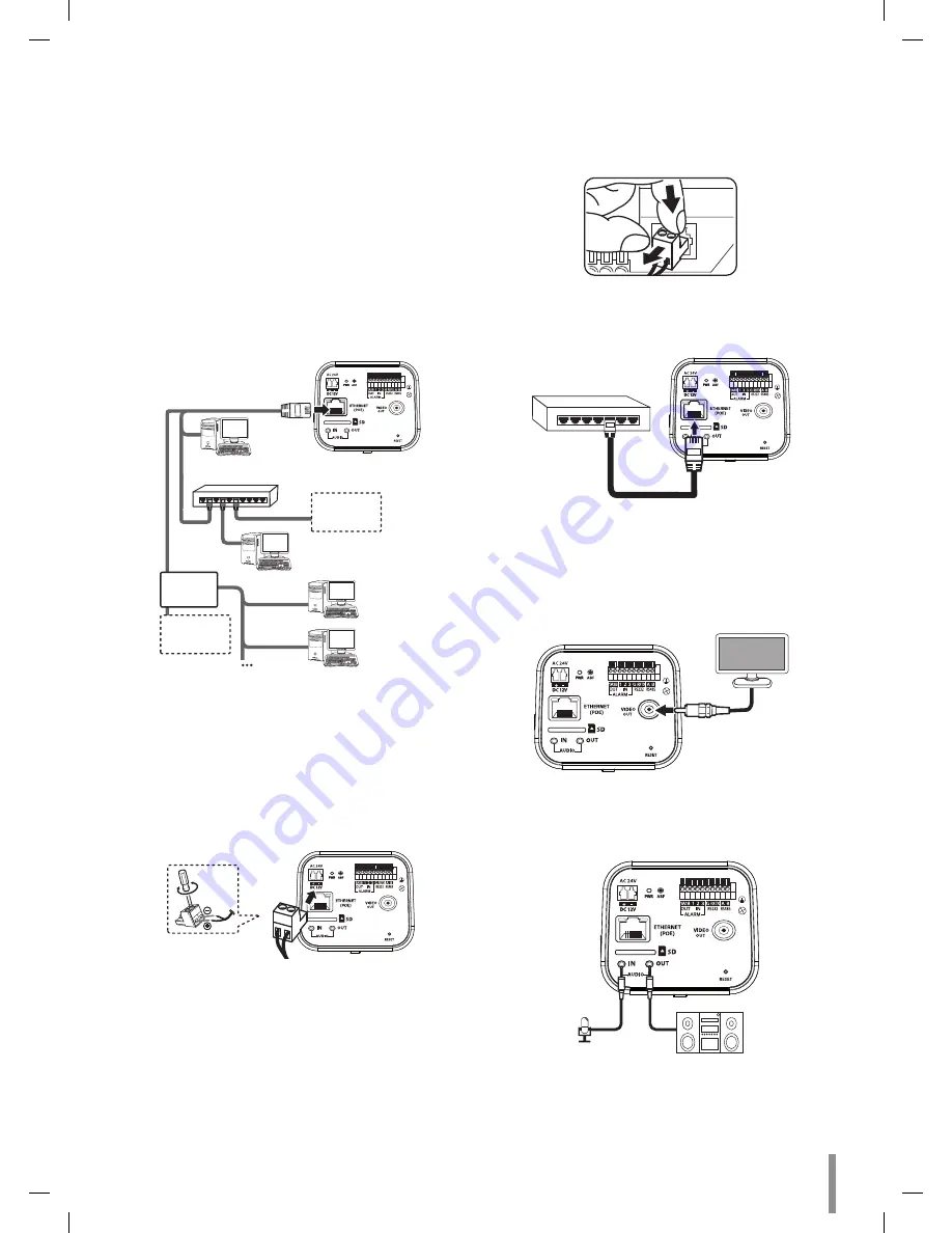
Connecting Network
You can control and monitor the system via network. With the remote
control (monitoring), you can change the system configuration or monitor
the image via network. After the installation, check the network settings
for the remote control and monitoring work.
Connect the IP camera to your network using a standard RJ-45 network
cable as shown below.
Broadband
Service
Broadband
Service
Router
PoE Device
(IEEE802.3af)
Connecting Power Source
Connect power, using one of the methods listed below:
To use the power adapter
Connect DC 12 V or AC 24 V power source to the power input terminal
as shown below. (recommended power adapter is DC 12 V or AC 24 V /
1.5 A or above).
Connect a power source to the power input terminal with
2
and
3
aligned correctly as shown below.
Note:
•
When connecting the power, tighten the screws as shown above.
•
To remove the connector plug, as shown below. Put your finger
between the power connector and the camera body to pull out the
connector.
POWER
1
2
3
+
-
To use the PoE (Power over Ethernet) device
Connect the PoE cable to the LAN port on the unit. You must use the
“IEEE802.3af” standard PoE device.
PoE Device
(IEEE802.3af)
Note:
If the camera doesn’t work properly after connecting PoE device, please
check if the PoE device supplies enough power.
Connecting Display Device
Connect the video signal between the IP camera and the monitor.
Connecting Microphone and Speaker Device
Optionally connect an active speaker and/or external microphone with a
built-in amplifier.
AUDIO IN
AUDIO OUT
Note:
Keep the microphone away from the speaker to avoid howling.
Summary of Contents for RNOE-B501A
Page 47: ......


