background image

ENGLISH

42

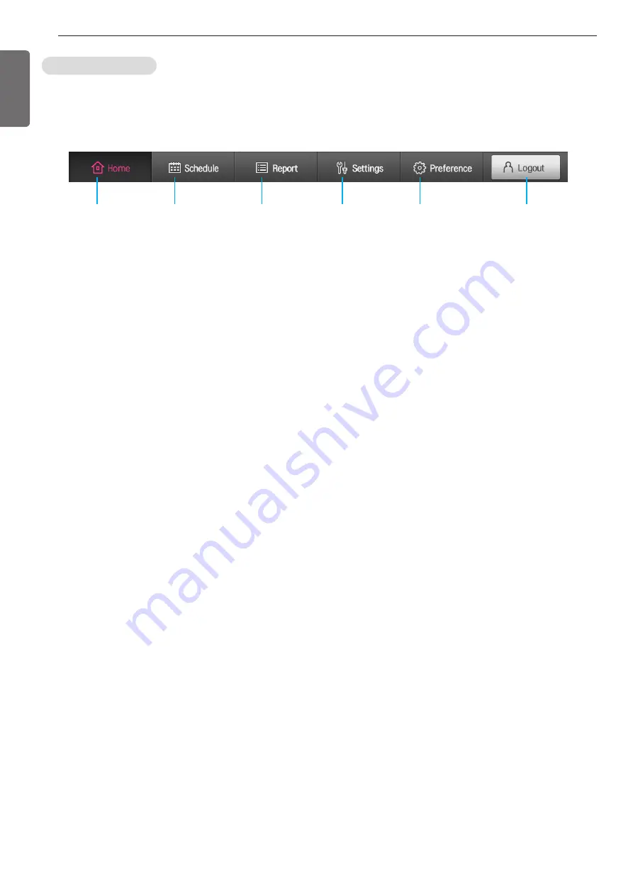
1.5. Bottom Menu

The bottom menu consists of the main menu and the login button at the bottom of the screen.

1. Home

Go to Home screen.

2. Schedule

Go to schedule screen.

3. History

Go to history screen.

4. Device setting

Go to user menu of device setting screen.

5. Environment setting

Go to language setting menu of the environment setting screen.

6. LOGIN/LOGOUT toggle button

Display LOGIN button when logged out.

Display LOGOUT button when logged in.

* Automatically log out when there is no control for 30 minutes after logging in.

1.Home

2. Schedule

3. History

4.Device setting

6.LOGIN

5. Environment

setting 

Figure 25. Bottom Menu

Summary of Contents for RCWFH Series

Page 1: ...ore use This content is to ensure the safety of users and to prevent property damages Keep the instruction manual in a place that is accessible to other users Only authorized people can use the product Model RCWFH Series 200 3000RT For AC Smart Premium Control System ENGLISH P NO MFL68929306 Rev 0 ...

Page 2: ...to this page in case you need it to prove the date of purchase or for warranty purposes Write the model number and the serial number here Model number Serial number You can find them on a label on the side of each unit Dealer s name Date of purchase ...

Page 3: ... Follow the direction 1 1 WARNING Have all electric work done by a licensed electrician according to Electric Facility Engineering Standard and Interior Wire Regulations and the instructions given in this manual and always use a special circuit If the power source capacity is inadequate or electric work is performed improperly electric shock or fire may re sult Ask the dealer or an authorized tech...

Page 4: ...injury Ventilate before operating the chiller unit when gas leaked out Do not use a phone or operate the power switch at this time It may cause fire or explosion Do not put any heavy object on the top of the unit or climb on the unit It may cause defects or injury Be careful with the rotating part Do not put your fingers or a stick to the rotating part It can cause injury Use the fuse and circuit ...

Page 5: ...it It may cause electric shock electricity leakage or defects Be careful of electric shock Always ground the chiller during installation It may cause electric shock Do not leave refrigerant system open to air any longer than necessary If the repair cannot be completed seal the circuits to prevent any contamination or rust within the product and charge dry nitrogen Do not reuse compressor oil It ca...

Page 6: ...eplacement first Do not use the product in special environments Oil steam and sulfuric steam can deteriorate the product performance or cause damage to the parts Be careful when transporting the product When carrying the chiller always consult with the specialized expert When transporting the chiller always follow the methods described in the manual If not it can cause overturn fall etc Do not tou...

Page 7: ...in the reverse direction will result in a compressor failure that will require compressor replacement Do not use jumpers or other tools to short out components or bypass the parts differently from recommended pro cedures Short circuiting the control board ground line with other wires can damage the electric module or electric compo nents Water must be within design flow limits and should be treate...

Page 8: ...Do not perform welding work near cables connected to the main unit Otherwise it may cause fire or damage Connect only the input output signal cables specified in the drawing to the control panel or starter panel Otherwise it may cause malfunction or damage Use the rated electrical cables If not it may cause fire or damage Use specified parts for repair If not it may cause fire or damage Install th...

Page 9: ...r Panel 27 4 3 Control Parts Attached on the Product 27 4 4 Basic Control Algorithm 28 4 5 BMS Support Function 28 4 6 Remote Control Signal and Status Sig nal Connection 29 4 7 Power Panel and Interface Signal 29 4 8 Central Monitoring Panel and Interface Signal 30 4 9 Start and Control Order 33 4 10 Product Protection Function 36 4 11 Checklists before inspection 37 4 12 Checklists after inspect...

Page 10: ...s Thus please refer to the approved drawings for the details 1 6 5 2 7 9 10 4 3 8 11 13 14 15 12 16 17 18 19 1 Terminal box for compressor motor 2 Actuator Variable diffuser 3 Actuator Vane motor 4 Oil separator 5 Relief valve for Evaporator 6 Relief valve for Condenser 7 Air Vent for Cooling water 8 Oil cooler 9 Drain for Chilled water 10 Drain for Cooling water 11 Control panel 12 Economizer sig...

Page 11: ...nser Power electricity Control electricity Temperatures of Chilled water inlet outlet Temperatures of Cooling water inlet outlet Maximum pressure of chilled water and cooling water 2 3 Nomenclature The nomenclature for the Fig 2 centrifugal chiller is as follows Combination Table Capacity Comp code Evap code Cond code Motor Power Con sumption Shipping weight Operation Weight Refrigerant weight RT ...

Page 12: ...1 82 83 84 85 86 87 88 89 90 16 1 16 7 17 2 17 8 18 3 18 9 19 4 20 0 20 6 21 1 21 7 22 2 22 8 23 3 23 9 24 4 25 0 25 6 26 1 26 7 27 2 27 8 28 3 28 9 29 4 30 0 30 6 31 1 31 7 32 2 91 92 93 94 95 96 97 98 99 100 101 102 103 104 105 106 107 108 109 110 111 112 113 114 115 116 117 118 119 120 32 8 33 3 33 9 34 4 35 0 35 6 36 1 36 7 37 2 37 9 38 3 38 9 39 4 40 0 40 6 41 1 41 7 42 2 42 8 43 3 43 9 44 4 ...

Page 13: ...13 114 115 116 117 118 119 120 5 695 5 765 5 836 5 906 5 976 6 046 6 117 6 187 6 257 6 328 6 398 6 468 6 539 6 609 6 679 6 750 6 820 6 890 6 968 7 031 7 101 7 171 7 242 7 312 7 382 7 453 7 523 7 593 7 663 7 734 7 804 7 874 7 945 8 015 8 085 8 156 8 226 8 296 8 367 8 437 121 122 123 124 125 126 127 128 129 130 131 132 133 134 135 136 137 138 139 140 141 142 143 144 145 146 147 148 149 150 151 152 1...

Page 14: ...zer which divides into gas and liquid of refrigerant The gas part is mixed with the mid temperature and mid pressured gas which was compressed in the 1st impeller and then enters the 2nd impeller The liquid part of the refrigerant enters the lower part of evaporator via 2nd orifice The liquid refrigerant entered into the evaporator is then spread into wider surface of evaporator by distributor Fi ...

Page 15: ...roduced 2 Bearing 1 Compressor type A0 E3 1 1 Ball bearing is composed of isolated bearing on motor axis and angular contact bearings on the impeller axis 1 2 Ball bearing structure is subjected to a radial and axial load at the same time 1 3 Because oil supply flow in ball bearing structure is small the rotation system is more compact design 2 Compressor type F1 G3 2 1 Bearing is composed of bear...

Page 16: ...e condenser If the refrigerant liquid level decreases more gas generated in the orifice and the resistance increased which becomes to control the flow rate The condensed refrigerant liquid passed the 1st orifice enters the economizer which divides into refrigerant gas and liquid The refrigerant gas is mixed with mid temper ature mid pressure gas compressed in the 1st impeller The refrigerant liqui...

Page 17: ...ressure different would be above 1 0 kg cm2 that is maintained by the oil pressure controller The differential pressure can be seen on the control panel pressure gauge display by the differential pressure between oil tank and oil pump The oil pump also helps to send the oil to the oil filter A valve is installed at the oil filter so that no need to drain the whole oil when replacing the filter onl...

Page 18: ... these problems into consideration An oil pump run by hermetic electro motor and a heater controlled by the controlling device are installed in the oil tank to prevent the trouble caused by the refrigerant inflow into the oil decrease of the viscosity damage of the pump caused by the cavitation vaporizing of water and formation of bubbles as becoming partially low pressurized when water or flow at...

Page 19: ...erature exceeds 85 C 1 7 Oil Differential Pressure Low Oil tank oil pump outlet Differential pressure of supplied and intake oil pressure If the differential pressure between the oil pres sure supplied to the bearing and the oil pressure in the oil tank is below 0 8kg cm2 the chiller will stop the operation 1 8 Oil Tempera ture High Oil tank Oil temperature in side of oil tank The chiller will sto...

Page 20: ...inlet of the impeller 1 16 Temperature Sensor Abnor mal 6 locations in cluding chilled water nozzle Each temperature sensor It alarms when temperature sensor is not con nected or due to the sensor s own flaw 1 17 Pressure Sen sor Abnormal 4 locations in cluding Evapo rator shell Each pressure sensor It alarms when pressure sensor is not connected or due to the sensor s own flaw 1 18 Overload relay...

Page 21: ...ut port DC 12V power input port LAN port LAN Cable connection port for Ethernet connection Support 100Mbps 10Mbps AC 24V input port AC 24V power input port Micro USB port Support port USB 2 0 for USB memory Stick connection Mini USB port for services PC connection power for S W upgrades Power ON OFF Control AC Smart Premium LCD backlight for pressing less than 10 seconds Reset AC Smart Premium sys...

Page 22: ...re They are used as Master or Slave by DIP switch settings SW4 OFF Master ON Slave Analog input output and digital input output consist of RS232 and RS485 communication connectors for the user s convenience Figure 11 Master Slave Board Internal Diagram MASTER SLAVE ...

Page 23: ...de vane and diffuser vain RS485 RS485 RS485 HMI SCREEN DISPLAY AND COMMUNICATION RELAY GUIDE DIFFUSER VANE CONTROL SLAVE TEMPERATURE PRESSURE DIGITAL INPUT OUTPUT CONTROL MASTER TEMPERATURE PRESSURE DIGITAL INPUT OUTPUT CONTROL UART DISPLAY UART BMS UART Slave MICOM PT100 INPUT 4 20mA INPUT 4 20mA OUTPUT DIGITAL INPUT DIGITAL OUTPUT UART BMS UART Slave UART DISPLAY MICOM DC 0 5V INPUT DIGITAL OUTP...

Page 24: ...iagram for details as the arrangement shown above may vary by model and change for design improvements and the user s convenience Fan TRANSFORMER NOIS FILTER FUSE MASTER SLAVE BOARD BREAKER RELAY BOARD RELAY MAGNETIC CONTACTOR SUMMER RELAY BUZZER TERMINAL BLOCK Figure 13 Control System ...

Page 25: ... Figure 14 Converter Table 5 LED Status Display LED name State Explanation TX485 RX485 Flicker Communication with the MYCOM works normally Off Error check communication lines TX232 RX232 Flicker Communication with BACnet works normally Off Error check communication lines RUN Flicker every second Board works normally after completing a Power On test Maintain On Off status Error Press reset button o...

Page 26: ...wing supplied with the product for an arrangement of the starter as the starter is arranged in various ways based on starting methods high low pressure power options etc Figure 15 6600V Reactor Starter Method h Please refer to the approved diagram for details as the arrangement shown above may vary by model and change for design improvements and the user s convenience FDS POWER FUSE BREAKER PT TRA...

Page 27: ...ng Approach a control goal by soft operation Resolved unnecessary emergency stop due to rapid guide vane opening which occur in operating Advanced control High precision control is realized by applying the far advance algorithm compared with existing PID control methods Prevent temperature Cycling phenomenon due to Over shoot Under shoot when converting from manual to auto matic mode Intensive Saf...

Page 28: ... 18 BMS Detail Drawing Figure 19 Control Signal h Minimum time to maintain start stop pulse maintain for at least 2 seconds 101 OPERATION DIC1 ON START STOP OPERATION SIGNAL CHILLER STATUS OFF CUSTOMER CONTROL BOARD CHILLER CONTROL BOARD 4 5 BMS Support Function The basic communication of the Turbo Chiller is Modbus protocol and it is compatible with higher communication methods Communication Prot...

Page 29: ... zero voltage This is the start stop signal of the pump or fan Access when operating by linking with start stop sig nals from the Chiller Use it at AC250V 0 1A re sistance load Signal name Signal type Signal meaning Notes Check motor operation Contact for signal Output contact of zero voltage ON when inputting opera tional signal OFF when inputting stop signal Use it at AC250V 0 1A re sistance loa...

Page 30: ...ENGLISH 30 4 9 Start and Control Order Turbo Chiller Signal Flow Graph Figure 20 Turbo Chiller Signal Flow Graph ...

Page 31: ...heck vane closed switch alarm Check operation oil temperature low alarm convert Check operation complete signal 2M abnormality Display soft operation and safety control message Check coolant pump interlock alarm Check coolant flow alarm Check coolant flow abnormality Check coolant pump interlock abnormality Check cold water pump interlock alarm Check cold water flow alarm Check cold water flow abn...

Page 32: ...nt differential pressure switch Oil pump start stop Compressor start stop Based on the one that operates first among vane closed switches soft stop settings or vane closed timer Operation complete signal 2M Message Signal ON OFF time 1 5 sec 120 sec 30 sec 300 sec RUN STOP RUN Vane closed timer when stopping Coolant pump stop timer Cold water stop and stop oil circulation timer Figure 21 Timing Se...

Page 33: ...ity Detected pump interlock abnormal ity when operating Detected pump interlock abnormal ity when operating Detected flow interlock abnormality when operating Detected flow interlock abnormality when operating Detected high oil temperature Detected high condenser pressure Detected low evaporator pressure Detected low evaporator refrigerant temperature Detected high condenser outlet temperature Det...

Page 34: ...lock setting 100 setting 2 Display high compressor outlet temperature block control cau tion message Caution Block high bearing temperature The guide vane closes when a bearing temperature goes above high tempera ture block setting 100 setting 2 Display high bearing tempera ture block control caution mes sage Caution Low cold water temperature block control The guide vane closes when a cold water ...

Page 35: ...s High bearing temperature contact closes The Chiller stops Abnormal High condenser pressure contact closes High condenser pressure contact closes The Chiller stops Abnormal Failure to operate No input signal for compressor opera tion complete The Chiller stops Abnormal Delta contactor opens when operating Starter contactor opens when operating The Chiller stops Abnormal Starter abnormality con ta...

Page 36: ...voltage stage with an electroscope and ground at needed spots c Take out circuit breakers to make short a circuit and attach display inspecting d Adjust disconnecting switches after cutting the power e Especially when the power is supplied with incoming distributing panel from a consumer automatic control or MCC board take measures in c and d above for those switches 5 Warnings about current and v...

Page 37: ...ailure status and dates when inspecting to utilize histo ries as reference for next inspection CAUTION Set the routine inspection to check loading operating hours and operating environment etc of the operating machine As the inspection period suggested in this manual is routine inspection establish inspection plans depending on the load of the machine and frequency of use Do not conduct insulation...

Page 38: ...onductor Is there any damage in the wires No abnormality Terminal Is there any damaged part No abnormality Relay contactor Is there any oscillation during operation Is there any damage on the connector No abnormality Space heater Is there any color change of the heater compo nent in starter panel No abnormality Sensor switch Is there any disconnection or short circuit Is there any damage in the co...

Page 39: ...VICE ENVIRONMENT SETTING GENERAL SETTING SCREEN SETTING CUSTOMER SETTING NETWORK SETTING ADVANCED SETTING CHANNEL SETTING LOG IN SCHEDULE VIEW SCHEDULE ADD EDIT SCHEDULE HISTORY VIEW HISTORY VIEW DETAILS Figure 22 Menu Structure Figure 23 Login Screen A touch keyboard appears at the bottom of the screen by touching the information input column Enter information using the touch keyboard ...

Page 40: ...hority LOG IN installer authority Top menu stop operating Top menu start operating X Top menu operation mode X Schedule add edit delete X History delete items X X Device setting user X Device setting user initialization of operating hours X X Device setting system X X Device setting device registration X X Environment setting general setting X Environment setting screen setting X Environment setti...

Page 41: ...ion operates the product remotely The control mode currently set is displayed on the screen 3 Setting temperature Display the temperature setting of the evaporator outlet 4 Operation status warning message Disable warning button Display the system operation status information and warning message Display the warning message and Disable Warning button message by expanding to the control mode tempera...

Page 42: ...ce setting Go to user menu of device setting screen 5 Environment setting Go to language setting menu of the environment setting screen 6 LOGIN LOGOUT toggle button Display LOGIN button when logged out Display LOGOUT button when logged in Automatically log out when there is no control for 30 minutes after logging in 1 Home 2 Schedule 3 History 4 Device setting 6 LOGIN 5 Environment setting Figure ...

Page 43: ...nual control button Provides manual control list 7 Animation Provides a current animation of the Chiller R134a 2Stage R123 8 Major information of the device Provides evaporator leaving water temperature and motor current Provides the same information when moving to other information tabs 9 Evaporator Provides evaporator entering water temperature leaving water tempera ture refrigerant temperature ...

Page 44: ...the device Displays evaporator leaving water temperature and motor current Provides same information when moving to other information tabs 3 Main information Provides evaporator pump interlock flow contact outlet water setting tem perature information 4 Additional information Displays evaporator entering water temperature leaving water tempera ture pressure refrigerant temperature LTD flow ECO lev...

Page 45: ...and flow Provides the same information when moving to other information tabs 3 Main information Provides inverter frequency one stage variable diffuser two stage variable diffuser hot gas valve information 4 Additional information Provides compressor inverter outlet current inverter outlet frequency in verter DC LINK voltage inverter temperature PID calculation motor winding R temperature motor wi...

Page 46: ... of the device Displays evaporator leaving water temperature and motor current Provides the same information when moving to other information tabs 3 Main information Provides condenser pump interlock flow contact pressure information 4 Additional information Provides condenser entering water temperature leaving water tempera ture pressure refrigerant temperature LTD CON level CON calculation CON v...

Page 47: ...ion when manual is selected by press ing the setting button 3 Hot gas valve Displays a hot valve value and provides manual automatic setting function and 0 100 control function when manual is selected by pressing the set ting button 4 Eco valve Displays a ECO valve value and provides manual automatic setting function and 0 100 control function when manual is selected by pressing the set ting butto...

Page 48: ...r Displays evaporator pump interlock ON OFF 18 Displays evaporator flow contact ON OFF 19 Displays evaporator outlet water setting temperature 3 digit and 1 decimal places XXX X C F 20 Displays remote temperature 3 digit and 1 decimal places XXX X C F Note 1 21 Displays evaporator entering water temperature 3 digit and 1 decimal places XXX X C F 22 Displays evaporator leaving water temperature 3 d...

Page 49: ...it and 1 decimal places XXX X C F 52 Displays condenser leaving water temperature 3 digit and 1 decimal places XXX X C F 53 Displays condenser pressure 4 digit and 2 decimal places XXXX XX kgf cm2 kPa psi 54 Displays condenser refrigerant temperature 3 digit and 1 decimal places XXX X C F 55 Displays LTD 3 digit and 1 decimal places XXX X C F 56 Displays condenser flow 4 digit places XXXX m3 h gal...

Page 50: ... 3 All schedule button Displays all schedule information lists that are currently stored on the de vice on the right side of schedule 4 Monthly navigation button Navigation to move to the last next month The left button and right button provide functions to go to the last month and next month respectively 5 Calendar year month Displays year month that the calendar is displaying 6 Add schedule You ...

Page 51: ...Cooling and ice manufacturing operation in case of ice thermal chiller Cooling and heating operation in case heat pump chiller is set 8 Motor current block Setting button that defines motor current block when implementing schedules Available to adjust in the range of 50 100 by pressing up down button 9 Cooling setting temperature Setting button that defines cooling setting temperature when impleme...

Page 52: ...data when selecting the operation button 3 Error category tab Provides list information corresponding to error data when selecting the error button 4 Report delete button Function to delete operation error data report Delete function is enabled when each operation error data checkbox is selected 5 Operation error history data Provides operation error occurrence date occurrence time device name cod...

Page 53: ...gure 34 View Details Table 18 View Details Items No Component Description 1 Error code Displays error code 2 Detailed information Displays error message information 3 Help Provides cause of error and help inspection and corrective actions ...

Page 54: ...s is to start stop the Chiller by using remote start stop zero voltage contact signal switch relay con tact signal from a remote area office on site or automatic control board Schedule This is to start stop the Chiller automatically according to scheduled programs by setting time and tem perature in the controller to start stop the Chiller 2 Select Operation Mode Standard Chiller Provides cooling ...

Page 55: ... mode 4 Fan inverter control of the cooling tower This is a control method to supply stable coolant inlet temperature and this is applied when an inverter is used in a fan motor control of the cooling tower Inverter should be selected for main menu system menu safety control setting cooling tower control of the control device Operation is available only when an inverter is attached on the user MCC...

Page 56: ...control action is under operation Current Block Action For example if the current block is set to 80 and rated current is 518A at point 1 when the current is 80 of the rated current as shown in the figure below vane opening stops and when the current reaches point 2 that is 105 of the current block setting the vane is closed until current goes down to point 1 When the current is lower than the poi...

Page 57: ...ass valve opens to 100 hot gas maximum setting 8 Hot Gas Maximum This is an item to set when applying the hot gas bypass valve This item is to set the maximum value of opening of the hot gas bypass valve and blocks the valve from opening larger than the setting If this value is set to 50 the hot gas bypass valve does not open larger than that value 9 Hot Gas Minimum This is an item to set when app...

Page 58: ... a number C 10 90 0 1 Operation Mode Heat 20 30 5 Operation Mode Cold Automatic operation Select a number C 0 10 0 1 Automatic tempera ture Select a number C 0 10 0 1 Hot gas vane Select a number 0 100 1 Hot gas maximum Select a number 1 100 1 Hot gas minimum Select a number 0 100 1 Guide vane Maxi mum Select a number C 1 100 1 Condenser entering water temperature Select a number C 10 50 0 1 Motor...

Page 59: ...ble 20 System Check Items Item name Setting avail ability Setting UI Unit Minimum value Maximum value Adjustment Unit Notes Master V Monitoring SW version Slave V Monitoring SW version Master C Monitoring PCB temper ature Slave C Monitoring PCB temper ature ...

Page 60: ... not input to the input terminal of the controller Mixed connection with other signal lines may damage the controller board 5 1 3 1 Master Figure 41 Input Status Check Master Table 21 Input status Check Master Items Item Name Setting availability Contact Action Status Notes Normal Condenser flow contact When flow is normal closed circuit ON OFF Evaporator pump interlock When pump operates closed c...

Page 61: ...N OFF High motor winding temperature contact When temperature is high closed circuit ON OFF Oil pump overload contact When there is overload closed circuit ON OFF Closed vane contact When vane closes closed circuit ON OFF Normal compressor motor power When power is supplied closed circuit ON OFF Compressor operation check When compressor operate closed circuit ON OFF Abnormal starter When there is...

Page 62: ...r Figure 43 Output Status Check Master Table 23 Output Status Check Master Items Control mode display When it is on ice manufacturing mode closed circuit ON OFF Remote selection display When selecting remote operation closed circuit ON OFF Evaporator water pump operation When pump operates closed circuit ON OFF Condenser water pump operation When pump operates closed circuit ON OFF Hot gas valve O...

Page 63: ...atus display When operating Closed circuit ON OFF Compressor abnormal stop When warning alarms Closed circuit ON OFF Abnormality status display When there is abnormality Closed circuit ON OFF Compressor run status When compressor operates Closed circuit ON OFF Compressor motor run When motor operates Closed circuit ON OFF Vane opening Diffuser opening 5 1 4 2 Slave Figure 44 Output Status Check Sl...

Page 64: ...umber of Chiller operation Rounds Hours of Chiller operation Hours Number of com pressor operation Rounds Hours of compres sor operation Hours No Component Description 1 Initialization button When logged in with the installer account chiller operation hours numbers are initialized to 0 by pressing the button 2 Initialization button When logged in with the installer account compressor operation hou...

Page 65: ... Chiller Item name Setting avail ability Setting UI Unit Minimum value Maximum value Adjustment Unit Notes Automatic restart Select a list Stop Restart Motor Amps Select a number A 0 3000 0 1 Refrigerant level use setting Select a list Use not use Control mode Select a list Unused Cold Heat Model selection Select a list 2stage R134a R123 Time block Select a list Use not use ...

Page 66: ... an evaporator pressure is lower than the setting when operating 3 High condenser pressure This is to set condenser pressure maximum The Chiller stops due to abnormality if a condenser pressure is lower than the setting when operating Table 28 Abnormality Condition Items Item Name Setting availability Setting UI Unit Minimum Value Maximum Value Adjustment Unit Notes Minimum Oil dif ferential press...

Page 67: ...value Maximum value Adjustment Unit Notes Automatic Control Setting Value Select a list Use Not use Surge High Pressure Select a number kgf cm2 0 18 0 01 Surge Low Pressure Select a number kgf cm2 0 18 0 01 Surge High Temperature Select a number C 0 12 0 01 Surge Low Temperature Select a number C 0 12 0 01 Soft Loading Period Select a number Seconds 1 60 1 Soft loading Output Select a number secon...

Page 68: ...ting UI Unit Minimum value Maximum value Adjustment Unit Notes Evaporator Water Pump Stop Select a number Seconds 1 1800 1 Condenser Water Pump Stop Select a number Seconds 1 1800 1 Ignore Flow Select a number Seconds 1 60 1 Oil Circulation Select a number Seconds 30 600 1 Check Compressor Run Select a number Seconds 5 60 1 Block Restart Select a number Seconds 5 3600 1 ...

Page 69: ...de vane dif fuser vane ECO valve CON valve to minimum maximum change the sensor setting mode to ON and then se lect corresponding setting minimum setting maximum setting to end the setting 5 2 5 1 Master Figure 50 Sensor Setting Master Table 31 Sensor Setting Master Items Item name Setting availability Setting UI Unit Minimum value Maximum value Adjustment Unit Notes Remote Temperature Setting Sel...

Page 70: ...djustment Unit Notes Sensor setting mode Select a list ON OFF Manual Automatic setting Button 0 100 1 Manual automatic Minimum Guide Vane Button 0 1023 Available when the sen sor setting mode is ON Available to press the minimum button Maximum Guide Vane button 0 1023 Available when the sen sor setting mode is ON Available to press the maximum button Guide Vane AD 0 1023 Monitoring ...

Page 71: ... Unit Notes Sensor setting mode Select a list ON OFF Manual Automatic setting Button 0 100 1 Manual automatic Diffuser Vane Minimum Button 0 1023 Available to use when the sensor setting mode is ON Available to press the minimum button Diffuser Vane Maximum button 0 1023 Available to use when the sensor setting mode is ON Available to press the maximum button Diffuser Vane AD value 0 1023 Monitori...

Page 72: ... Unit Notes Sensor Setting Mode Select a list ON OFF Manual Automatic Setting Button 0 100 1 Manual Automatic ECO Valve Minimum Button 0 1023 Available to use when the sensor setting mode is ON Available to press the minimum button ECO Valve Maximum button 0 1023 Available to use when the sensor setting mode is ON Available to press the maximum button ECO Valve AD value 0 1023 Monitoring ...

Page 73: ...nt Unit Notes Sensor Setting Mode Select a list ON OFF Manual Automatic setting Button 0 100 1 Manual automatic CON Valve Minimum Button 0 1023 Available to use when the sensor setting mode is ON Available to press the minimum button CON Valve Maximum button 0 1023 Available to use when the sensor setting mode is ON Available to press the maximum button CON Valve AD value 0 1023 Monitoring ...

Page 74: ...mum value Adjustment Unit Notes Sensor Setting Mode Select a list ON OFF Manual Automatic Setting Button 0 100 1 Manual Automatic ECO Valve Minimum Button 0 1023 Available to use when the sensor setting mode is ON Available to press the minimum button ECO Valve Maximum button 0 1023 Available to use when the sensor setting mode is ON Available to press the maximum button ECO Valve AD value 0 1023 ...

Page 75: ...imum value Maximum value Adjustment Unit Notes Sensor Setting Mode Select a list ON OFF Manual Automatic setting Button 0 100 1 Manual automatic CON Valve Minimum Button 0 1023 Available to use when the sensor setting mode is ON Available to press the minimum button CON Valve Maximum button 0 1023 Available to use when the sensor setting mode is ON Available to press the maximum button CON Valve A...

Page 76: ...Setting availability Setting UI Unit Minimum value Maximum value Adjustment Unit Notes CON Refrigerant Level Setting Select a number 0 100 0 1 CON Refrigerant Valve Default Select a number 0 100 0 1 CON Refrigerant Level P Select a number 0 100 0 1 CON Refrigerant Level I Select a number seconds 0 3600 1 CON Refrigerant Dead Zone Select a number 0 100 0 1 ...

Page 77: ...aster Table 39 Option Setting Master Items Item name Setting availability Setting UI Unit Minimum value Maximum value Adjustment Unit Notes Remote Setting Temperature Select a list Use not use Hot Gas Valve Select a list Use not use Evaporator Water Flow Select a list Use not use Condenser Water Flow Select a list Use not use ...

Page 78: ...ng UI Unit Minimum value Maximum value Adjustment Unit Notes Motor Winding R temperature Select a list Use not use Motor Winding S temperature Select a list Use not use Motor Winding T temperature Select a list Use not use Oil Tank Pressure Select a list Use not use Power Select a list Use not use Vibration Select a list Use not use ...

Page 79: ... Table 41 Option Setting Relay Item List Item name Setting availability Setting UI Unit Minimum value Maximum value Adjustment Unit Notes Diffuser Vane Sensor Select a list Use not use ECO Valve Select a list Use not use CON Valve Select a list Use not use ...

Page 80: ...l Setting Items No Component Description 1 Language Provides the evaporator animation Provides lists of languages for setting Korean English Chinese 2 Time Setting Displays the time of the HMI system Provides a setting list pop up when selected 3 Date Setting Displays the date of the HMI system Provides a time setting pop up when selected 4 Holiday Setting Sets holidays that schedules do not work ...

Page 81: ...an English Chinese settings are available 1 Log in and press General Settings Language 2 Language change is completed by pressing Apply after selecting the desired language Figure 62 Language Selection List Figure 63 Language Setting Korean ...

Page 82: ...ENGLISH 82 Figure 64 Language Setting English Figure 65 Language Setting Chinese ...

Page 83: ... for the screen saver Sets a waiting time with a list menu among 10 20 30 40 50 and 60 minutes 2 Speaker Setting Sets use not use for the speaker 3 Backlight Power Setting Sets use not use for the backlight Sets a waiting time with a list menu among 10 20 30 40 50 and 60 minutes 4 Screen Calibration Screen calibration menu for accuracy of screen touch ...

Page 84: ...s Table 44 Customer Settings Item List No Component Description 1 General Settings Menu to change the password for currently logged in account and to add an administra tor account 2 User Management Menu to delete or edit change password other administrator accounts ...

Page 85: ... Account 1 Log in with the installer account 2 Select Environment Settings Customer Settings Add User 3 Enter ID Password Password Confirm in the Add User pop up and press Confirm button Figure 68 Add User Figure 69 Add User Pop Up ...

Page 86: ... 86 4 An Administrator Account with ID entered in the pop up is created when pressing Confirm button 5 Log out and log in as the Administrator account Figure 70 Administrator Account Creation Figure 71 Log In ...

Page 87: ... Figure 72 Network Settings Table 45 Network Setting Item List No Component Description 1 IP Address Settings Set an IP address setting method 2 IP Information Enter IP address subnet mask gateway 3 DNS Server Enter Main DNS Sub DNS ...

Page 88: ...d to the HMI system Provides an unit setting list pop up when se lected Temperature Units C F Pressure Units kgf cm2 kPa psi Flow Units m3 h gal min 2 Update S W Provides a function to upgrade the system to a new S W when selected Only when SD CARD with a new S W is inserted 3 DB management Provides a function to manage DB that is used in the HMI system 1 2 3 ...

Page 89: ...nel Settings Figure 74 Channel Settings Table 47 Channel Settings Item No Component Description 1 Channel Settings Provides a function to set a communication speed of CH1 CH2 Communication speed MODBUS_9600 MODBUS_19200 1 ...

Page 90: ...Displays the device name operation state operation mode vane opening evaporator leaving temperature motor current condenser leaving temperature information Table 49 Data Storage Item Component Description Data Storage Generate important data in every 5 seconds Compressed to Year_Month Day tar gz ex 2013_01_01 tar gz form in a SD card ...

Page 91: ...ller by remotely accessing it on the Web 1 Connect LAN to HMI LAN port 2 Select Environment Settings Network Settings IP Address Settings 3 Press Apply button after selecting Get the IP address using DHCP in the IP Address Setting Pop up Figure 76 Network Settings Figure 77 IP Address Settings ...

Page 92: ... IP address of the IP information in the Internet address bar in the form at http IPaddress Figure 78 IP address of IP Information Figure 79 Enter IP address in the Internet Address Bar 5 HMI screen is displayed on the Web Figure 80 Web Access Screen ...

Page 93: ...starter and controller panel Function test for safety devices Check before start up Check before and after start up Run chilled water pump Run cooling water pump Charging Nitrogen gas If a month or more left until operation Dissatisfaction Wiring construction between starter panel and control panel The order can be changed Installation of Foundation foundation panel Receipt and Installation Insula...

Page 94: ...humid Provide ample space for service for control and maintenance of pipes and tubes Foundation Build the foundation to withstand the concentrated heavy weight of the chiller The foundation should be higher than the surface of the water and install the drainage around Be sure to install the drain pipe to the drainage hole Receipt and Installation The chiller should be installed evenly leveled to t...

Page 95: ...he first run after receipt and installation or the run after long term stoppage over 1 month before the regular operation of the chiller Preparation for start up is the maintenance and repairing work at least once a year after installation which is a very basic and important task Checking the leak parts It is recommended to perform leakage test following the steps in Fig 58 Refer to the temperatur...

Page 96: ...ry connecting part 3 If the inspected pressure lasts for more than 30 min prepare to do the soapy water test for smaller parts 4 Mark the leaking point 5 Eject the inner pressure of the machine 6 Fix all the leaking points 7 Do leak test again on the repaired points 8 After performing the large leaking test increase the inner pressure up to the value of 9 9 5 kg cm2 9 Do the small leak test and fi...

Page 97: ... 28 6 3819 64 17 784 7 1 2713 29 6 6001 65 18 223 6 1 3610 30 6 8231 66 18 670 5 1 4535 31 7 0510 67 19 124 4 1 5486 32 7 2838 68 19 587 3 1 6466 33 7 5216 69 20 057 2 1 7474 34 7 7644 70 20 536 1 1 8512 35 8 0124 71 21 023 0 1 9579 36 8 2657 72 21 518 1 2 0675 37 8 5242 73 22 023 2 2 1803 38 8 788 74 22 535 3 2 2962 39 9 0578 75 23 057 4 2 4153 40 9 3318 76 23 587 5 2 5376 41 9 6128 77 24 127 6 2...

Page 98: ... to external 4 Allow approximately 2 hours of additional vacuum pump operation if the surrounding temperature of the ma chine is above 15 6 C and while the vacuum pump is operated if the manometer is indicating 756mmHg If the internal pressure of the chiller is kept below 756 mmHg the accumulated moist in the machine would be frozen and then this ice is evaporated more slowly than in normal condit...

Page 99: ...oil foaming may be happening 4 Be cautious not to let any air enter into during oil charging Insulation resistance test 1 Mega test is to apply the direct voltage to the insulation material to obtain insulation resistance by measuring the leaking current through the material For 3000 and 6000V class use mega for 1000V For 380 and 440V class use mega for 500V 2 Keep away any unnecessary personnel d...

Page 100: ...emperature coefficient and convert the value indicated after a minute 9 Taking measures according to insulated condition Temp of insulation body at inspection C Value indicated after a minute Action Danger Below 2 MΩ Repair or Exchange Bad Below 50 MΩ Troubleshooting Re inspection 50 100 MΩ Troubleshooting Good 100 500 MΩ Better 500 1000 MΩ Excellent Above 1000 MΩ Condition Insulation Absorption R...

Page 101: ...y connected Special checking should be taken to power line 2 Check the display condition after control power in Be more cautious if there is any symptom of getting short for 5 seconds after the power is in If problem occurs immediately cut the power and check for abnormality 3 Check values displayed on the panel Check if the display indicating sensor values are normal If the sensor indicates abnor...

Page 102: ...Auto The vane is to maintain 0 on any condition of Auto Open Stop Closed when the chiller stops 4 Set the oil pump condition of the control panel to Auto 5 Activate the chilled water pump When operating close the outlet valve open the air ventilation valve and then open the outlet valve to a small carefully to avoid water hammering so that necessary amount of flow passes through If water keeps com...

Page 103: ...r If the direction is opposite stop the chiller and change the two among three phases Starting Characteristic Check the starting current acceleration completion time as on the Check List 4 Check the Operating Current 5 Motor Cooling Status Operating Current After the start up is done the vane will be opened gradually and the current increases simultaneously Operation current should not exceed the ...

Page 104: ...ated automatically The oil pump will perform additional operation even after the chiller s shut down The purpose of this action is to preserve the oil pressure for inertia operation of about 1 min after the chiller shut down and to protect the electromotor from frequent start and stoppage Load Operation and the Operational Setup After the Start and the Stoppage operation perform the Load Operation...

Page 105: ...Assemble condition of the Gear Foreign substance in the gear box End play of the impeller shaft Assemble condition of the guide vane Check the vane and the drive shaft Check the gap between the impeller and the cover with a thickness gauge 2 Lubrication system Loosen and crack of the oil pipe Replacing or clearing the oil filter Cleaning the oil tank Replacing the oil 3 Refrigeration System Check ...

Page 106: ...l stop after the chiller s shutdown the delay time due to motor s inertia moment 3 Check the oil pump remaining operation Check if the oil pump is operating till a resolved time after the chiller s shut down 4 Checklist after stoppage Stop the cooling water pump In this case close the outlet valve of the pump grad ually and then stop the cooling water pump Stop the chilled water pump Close the out...

Page 107: ...riod of Abrasion after a certain period of time If it enters to the Period of Abrasion region possibility of the machine s failure is going to rise up Thus it is very essential to take thorough overhaul repairing action will prevent accidents and allow an optimum maintenance We recommend on the basis of a long term experience and statistical data that you take the thorough overhaul re pairing acti...

Page 108: ...e veloped 3 Quickness As machine status can be always checked through a regular inspection precise instruction can be given to even a trouble notice by phone call Maintenance Contract machines will get the premium service as the first creditor even during the rush season when there are plenty of service loads Maintenance Contract Work Details Standard 1 Inspection before the start cooling 1 Air ti...

Page 109: ...rs Replacing 7 Oil extraction 8 Air tightness test 9 Electricity relate insulation test 10 Function test between Starter panel Control panel 11 Checking the oil pump 12 Chiller operation setup Compressor 1 Compressor Overhaul repair 1 Preparation 2 Disassemble Compressor 3 Check capacity controlling device 4 Inspection over the Compressor parts and cleaning 5 High speed gear inspection 6 Inspectin...

Page 110: ...Assemble Standard Contract Disassemble Inspection Repairing Parts 1 Compressor 1 Bearing 2 Shaft labyrinth 3 Impeller shim 1st level 2nd level 4 O ring Gasket 5 Oil filter 2 Motor 1 Bearing 2 Rear cover 3 O ring Gasket 4 Filter Drier Moisture Indicator The Others 1 Compressor 1 Impeller 2 Diffuser 3 Impeller cover 4 Impeller shaft 5 Return channel 1 2 3 6 Gear 7 Plate type Heat exchanger 8 Capacit...

Page 111: ... with the thermometer Able to see the refriger ant flow Motor Drain Oil Flow Measure using Differential Pressure Able to see the refriger ant flow Compressor discharge gas temp Check temp at the control panel Able to see the refriger ant flow Vibration noise Check with the hand and Ear Measure using the vibration measuring instrument if necessary Noise Below 85dB When there s no abnormal vibration...

Page 112: ...d cooling water outlet temp Evaporator daily inspection standards When evaporation pressure is decreased the evaporator tube freezes and eventually damaged or compressor surge would also be possible Causes of the decreased evaporating pressure would be insufficient refrigerant quantity low temperature water and abnormal heat exchanging efficiency Like the condenser tubes if foreign substances are ...

Page 113: ...ank and the pressure at that time would be above 0 8kg cm2 The oil pump is sending the oil to the oil filter where a valve is installed so that there is no need to drain the whole system when replacing the filter Afterwards the oil is sent to the oil cooler and then cooled by the refrigerant from the condenser The refrigerant cools off the oil as low as 30 60 C Oil that left the cooler passes thro...

Page 114: ... 2 Y Δ start up 3 Kondorfer start up 4 Reactor start up In case of chilled water outlet temp _ C Time of start up current flow t 5 25 sec Start up current A Timer set value sec Figure 91 Compressor and motor monthly inspection standard Figure 92 Lubrication system monthly inspection standard Generally the starting current of the motor is about 600 that of the rated current in direct input And in c...

Page 115: ...st gas of chemical plants such as ammonia or petroleum gas etc deterio rates the water quality even more These pollutant causes can corrode the pipe scales adhered causes the tubes to have holes and lockouts which are leading to a decreasing effect of heat exchanger Therefore it may end to replacing the tubes increased power cost or the chiller failure Thus cooling water quality must be maintained...

Page 116: ...ted pH 25 C Electric conductivity Ma m 25 C cm 25 C Chloride ion mgCl L Sulfuric ion mgSO4 2 L Acid consumption pH4 8 mgCaCO3 L Total hardness mgCaCO3 L Calcium hardness mgCaCO3 L Ion silica mgSiO2 L Iron mgFe L Copper mgCu L Sulfide ion mgSO2 L Ammonium ion mgNH4 L Residual chlorine mgCl L Free carbon dioxide mgCO2 L Stability index 6 5 8 2 6 0 8 0 6 8 8 0 6 8 8 0 6 8 8 0 ㅇ ㅇ ㅇ ㅇ below 200 below ...

Page 117: ...take of air into the machine store the machine with about 5kg refrigerant charged or to apply 0 5kg nitrogen 3 If the place where the machine is installed goes below 0 C frequently to prevent the freezing drain the cooling water chilled water and condensed water Also open the waterbox drain 4 Leave the oil charged in the machine and to maintain the minimum oil tank temperature supply power to the ...

Page 118: ...re Kondorfer reactor Actual measurement Start up time T 5 25 sec t sec sec C A Touch the surface of the motor with hand Measured at 1000V Check opening 0 100 Check opening status Check opening ratio Check current value After chiller is stopped check from half load side of the motor when the meter axes stopped time Measure the surface of the bolts with thermometer Touch with hand or check with ears...

Page 119: ...arging new refrigerant Visual inspection Visual inspection Check through sight glass Difference between chilled water outlet temp and evaporating temp Check with manometer thermometer Check with thermometer Check with thermometer Difference between condensing temp and cooling water outlet temp Check with manometer thermometer Check with thermometer Check with thermometer 34 C or less standard cond...

Page 120: ...KW Rated current A Inspection date Year Month Day Note 1 The manufacturer is not responsible for the problems happened due to the reasons as follows poor water quality customer s poor maintenance and natural disaster 2 Overhaul for the compressor should be done in 5 years or in 10000 hours whichever comes first 3 Beware that some items can be changed without prior notice for the product improvemen...

Page 121: ...Lubrication friction loss sealing effect cooling capability 100 C 8 29 Viscosity index 90 Relationship to the viscosity change due to temp change Total acid value 0 01 Measure oxidation of the oil itself compared to the initial total acid value Corrosion of the copper plate 1 Anti corrosion ability of the oil 100 C 3h Available oils Oil from LG Japan sun oil Icecold SW68 Castrol Castrol Icematic S...

Page 122: ...rcuit breaker is opened 2 Shut down the oil pump power 3 Close the oil filter separator valves 4 When opening the oil filter housing do it slowly 5 Make vacuum in the filter housing after the filter exchange or assembling After the vacuum has been done open the separation valve and if there is insufficient amount of oil add oil through the charging valve CAUTION Decrease the pressure of the oil fi...

Page 123: ... temperature so it requires the refrigerant leak test utilizing elec tronic detector halogen leak detector or soapy water If the refrigerant leak is overall the entire chiller with large volume immediately stop using the system and fix it first If the refrigerant was lost or the machine has been opened during the service period the chiller itself or re lated tank must be taken leak test by adding ...

Page 124: ... Condenser Inspect Heat exchanger tubes Evaporator When the first operation season is over clean the evaporator tubes These tubes have foreign substances inside Thus to clean the tubes thoroughly a special caution should be exer cised The tubes condition at this time will become the data to determine how often tubes needs to be cleaned and whether the water treatment in the chilled water brine sys...

Page 125: ...etc are properly connected Special checking should be taken to power line 2 After power on check the display status of the panel Pay special attention if there is any sign of short circuit for about 5 sec after power on If any of the following symptoms occur immediately disconnect power and check for problem 3 Check values displayed on the panel Check whether each sensor value displayed on the pan...

Page 126: ...in board malfunction Check parts status or wiring Replace parts or re wire Bearing temperature sensor Bearing temperature sen sor problem Sensor disconnected short circuit Main board malfunction Check parts status or wiring Replace parts or re wire Motor winding R phase temperature sensor Motor winding R phase temperature sensor error Sensor disconnected short circuit Main board malfunction Check ...

Page 127: ...utlet temp Chilled water temp low Error Chilled water outlet temp is detected to be below set value There is no or small cooling load Check chilled water outlet temp or temp on the thermometer Check the set value and correct if it is wrong Evaporator pressure Evaporator pressure low Evaporator pressure is de tected to be below set value Check evaporator pressure displayed on the controller screen ...

Page 128: ...sure switch setting problem Wrong wiring IO board malfunction Correct set value and check Check parts status or wiring Replace parts or re wire Cooling water flow interlock Cooling water flow low abnormal Pump interlock signal is dis connected during normal op eration Pump stopped Wrong wiring IO board malfunction Check parts status or wiring Replace parts or re wire Start up competed signal 2M De...

Page 129: ...ane sensor is OK Also measure resistance between a b c and main body and it shall not be angle line If the vane sensor is normal re connect the sensor completely close the vane and check if vane value is 0 and 100 after completely opening If the value changes and vane opening is wrong sensor needs to be set again If there is no change of value check if 100 is set in sensor setting guide vane setti...

Page 130: ... check the main power of the main board again and if power is normal and there is no sensor input value Master or slave board needs to be replaced Temp C Rt Ω Temp C Rt Ω Temp C Rt Ω Temp C Rt Ω 200 18 52 20 107 79 240 90 47 450 264 18 190 22 83 30 111 67 250 194 1 460 267 56 180 27 1 40 115 54 260 197 71 470 270 93 170 31 34 50 119 4 270 201 31 480 274 29 160 35 54 60 123 24 280 204 9 490 277 64 ...

Page 131: ...it properly set Measure current of the circuit Refer to Figure 99 Is there current proportional to the measurement value Measure the current of the sensor Refer to Figure 100 Is the current of the sensor normal Check if the wiring between sensor and controller is properly connected Sensor Error Check subsidiary power If subsidiary power is normal replace the sensor Master board slave board display...

Page 132: ... within DC 22V 5 DC24V Even if the inspection was carried out as above if the cause couldn t be found connect current generator to the input connector DC24V and of the controller and check if the indicator value changes according to the change of the current In such case if the controller indicator value does not change according to the change of the current it shall be de cided as controller defe...

Page 133: ...onnector of the wiring among the controller digital inputs that does not work to COM connector 23 24 of controller I O board to check whether LED LAMP corresponding to the I O board input connector is lighted Select menu key system information I O input of the controller display short circuit open abnormal con nectors and COM connector to see if input status changes to ON OFF When DC voltage betwe...

Page 134: ...rly connected Is I O board voltage normal Check communication connection status between master board and slave board Is the main power of controller normal Replace main board Measure voltage of the controller refer to Figure 103 Is connector connection normal Connect the cable firmly again Replace I O board Check normal operation of related wires and input sensor N N N N N Y Y Y Y Y Figure 101 Dig...

Page 135: ...The current measurement circuit for master or slave board Communication error It is the error caused by no communication corresponding to the displayed message is made between each board First check communication line connection status between each board At this time 2 RDX and RDX lines of mas ter board shall be connected to the same polarity of RDX and RDX of slave board and relay board and 2 RDX...

Page 136: ... cooling water pump intake 1 Check the cooling water system and increase to specified amount 2 Enhance pump intake Table 63 Master or Slave board current measurement circuit Abnormal drop of evaporator pressure cause of surge Status Decision criteria Cause Remedy Evaporating pressure is low and chilled water inlet outlet tem perature differ ence is small 1 Butterfly valve adjustment defect 2 Insuf...

Page 137: ... Adjust set value 3 Check condensed refrigerant amount and filter drier 4 Remove oil to make it adequate amount 5 Need disassembly and repair Rapid change of oil pressure 1 Oil manometer defect 2 Oil pump cavitation 3 Insufficient oil 1 Change manometer 2 Apply power to oil heater 3 Recharge oil Oil tank temp is low Below 30 C 1 Oil heater fuse disconnected 2 Oil heater disconnected 3 Black out fo...

Page 138: ...dy 1 Contact of the rotating part 2 Bearing abrasion damage 1 Need to disassemble and repair 2 Need to disassemble and repair Abnormal sound 1 Noise transferred from cooling water and chilled water pipe 2 Guide vane assembly defect 3 Isolation device defect 1 Apply flexible join and spring isolator in the pipes 2 Reassemble or replacement 3 Replace isolator device Moisture indica tor turns yellow ...

Page 139: ...pora tor Pressure kg cm2 Refrigerant temp C Cooling water Inlet pressure kg cm2 Outlet pressure kg cm2 Inlet temp C Outlet temp C Cooling W Flow m3 h Con denser Pressure kg cm2 Refrigerant temp C Oil TANK pressure kg cm2 PUMP pressure kg cm2 Differential pressure kg cm2 Temp C Compres sor Current limit value Operating current A Winding temp C Temp of Bearing C Discharge gas temp C Vane opening Dif...

Page 140: ......

Reviews: