background image

2

SAFETY INSTRUCTIONS

ENGLISH

WARNING

• Installation or repairs made by unqualified persons can result in

hazards to you and others.

• The information contained in the manual is intended for use by a

qualified service technician familiar with safety procedures and
equipped with the proper tools and test instruments.

• Failure to carefully read and follow all instructions in this manual

can result in equipment malfunction, property damage, personal
injury and/or death.

Installation

• For installation of the product, always contact the service center or

a professional installation agency.
- Otherwise, it may cause fire, electrical shock, explosion or injury.

!

WARNING

This indicates that the failure to follow the instructions can
cause serious injury or death.

CAUTION

This indicates that the failure to follow the instructions can
cause the minor injury or damage to the product.

This symbol is displayed to indicate matters and operations
that can cause risk. 
Read the part with this symbol carefully and follow the
instructions in order to avoid risk.

!

!

!

SAFETY INSTRUCTIONS

The following safety guidelines are intended to prevent unforeseen
risks or damage from unsafe or incorrect operation of the appliance.
The guidelines are separated into ‘WARNING’ and ‘CAUTION’ as
described below.

Summary of Contents for PAHCMR000

Page 1: ...ce after reading it thoroughly Representative LG Electronics Inc EU Representative LG Electronics European Shared Service Center B V Krijgsman 1 1186 DM Amstelveen The Netherlands Manufacturer LG Electronics Inc Changwon 2nd factory 84 Wanam ro Seongsan gu Changwon si Gyeongsangnam do KOREA MFL69940001 Rev 02_020420 Applied AHU AHU CONTROLLER Original instruction www lg com Copyright 2017 2020 LG ...

Page 2: ...ce center or a professional installation agency Otherwise it may cause fire electrical shock explosion or injury WARNING This indicates that the failure to follow the instructions can cause serious injury or death CAUTION This indicates that the failure to follow the instructions can cause the minor injury or damage to the product This symbol is displayed to indicate matters and operations that ca...

Page 3: ... install the product in a place where there is the concern of falling down Otherwise it may result in personal injury Use caution when unpacking and installing Sharp edges may cause injury Always ground the product There is risk of fire or electric shock Do not install the product on a non parallel or defective installation stand It may cause injury accident or damage to the product Operation Keep...

Page 4: ...in or soil pipe Bad smells can occur and it results in a corrosion of a heat exchanger or pipe Operation This appliance is not intended for use by persons including children with reduced physical sensory or mental capabilities or lack of experience and knowledge unless they have been given supervision or instruction concerning use of the appliance by a person responsible for their safety Children ...

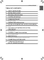
Page 5: ...ORS INSTALLATION 12 RETURN AIR TEMPERATURE CONTROL PAHCMR000 12 DIP SW 21 DISCHARGE AIR TEMPERATURE CONTROL PAHCMS000 21 Main Module DIP SW 31 EXTERNAL CONNECTION DIAGRAM 31 Return air temperature control 35 BMS PROTOCOL 35 BACnet points of PAHCMR000 Return air temperature control 41 CONNECTION SETTING GUIDE 44 COMMUNICATION MODULE EEV KIT CONNECTION GUIDE TABLE OF CONTENTS ...

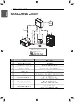
Page 6: ...ling Unit Local supply AHU Communication kit PAHCMS000 PAHCMR000 Remote controller LG wired remote controller Optional Outdoor unit MULTI V EEV Kit PRLK048A0 PRLK096A0 PRLK396A0 PRLK594A0 Pipe in Liquid thermistor Sensor Ø 5 NTC 5 kΩ length 5 m Cable color Black Pipe out Gas thermistor Sensor Ø 7 NTC 5 kΩ length 5 m Cable color Red Room Return thermistor Sensor NTC 10 kΩ length 5 m Cable color Bla...

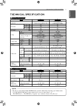
Page 7: ... Power Supply Screw type L N Ring type Screw type L N Ring type Communication Spring push type Pin type JOBN153 Spring push type Pin type JOBN153 Temp Sensor Air Room Q ty 1 EA Pin type 5m Black Q ty 1 EA Pin type 5m Black Key EA 1 1 Installation Manual EA 1 1 Product Environment Operation Range Ambient Temperature 20 65 C DB 20 65 C DB Humidity 0 98 0 98 NOTE Maximum connectable PAHCMR000 Communi...

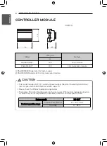
Page 8: ...6 and NEC Class 2 Please check the Product operation range below The Ingress Protection Marking given in this manual as IP20 restricts installation location LG Electronics is not responsible for installation locations non compliant to IP20 Power supply DC 12 V Product operation range Ambient Temperature 20 65 C DB Humidity 0 98 Unit mm 1 PAHCMM000 Model refer for Main module 2 PAHCMC000 Model refe...

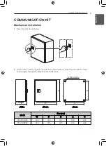
Page 9: ...tion 1 Open the door using the key 2 Drill 4 holes on correct position and fix the Communication Kit box securely with 4 screws Field supply through the holes Ø 9 mm 11 32 inch Side Front Rear Model Size mm W D H A B PAHCMR000 300 155 300 260 260 PAHCMS000 380 155 300 340 260 ...

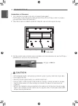
Page 10: ...to connect to the terminal block DEOH LQVHUW Pin type JOBN153 CAUTION All field supplied parts and materials and electric works must be conform to local codes Use copper wire only All wiring must be performed by an authorized electrician A main switch or other means for disconnection having a contact separation in all poles must be incorporated in the fixed wiring in accordance to relevant local a...

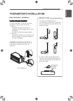
Page 11: ...ssible to the heat exchanger Evaluation must be done to check if the evaporator is protected against freeze up Execute test operation and check for freeze up 1 Ø6 3 Ø8 2 2 Air handling unit INSTRUCTION To prevent condensation from accumulating on the bottom of the pipe sensor install the sensor by lifting it up as shown below In order to detect the temperature of the pipe well install the sensing ...

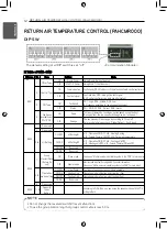
Page 12: ...d SW2 1 Reserved 2 Reserved 3 4 UI Setting OFF OFF UI Setting 1 UI1 Operation ON OFF UI2 Heating Cooling UI3 Forced Thermal ON OFF UI4 Target air temperature OFF ON UI Setting 2 UI1 Operation ON OFF UI2 Cooling only OFF UI3 Heating only OFF UI4 Forced Thermal ON and OFF ON OFF Reserved ON ON Reserved SW3 1 Group Master Slave Return Air only ON Slave mode Please see Multiple module installation gui...

Page 13: ... Setting No SW4 DIP switch Capacity kBTU hr Capacity kW MULTI V Single MULTI V Single 1 12 5 3 5 1 5 2 15 7 4 5 2 1 3 18 9 5 6 2 5 4 24 12 7 1 3 5 5 28 15 8 2 4 2 6 36 18 10 6 5 0 7 42 24 12 3 7 1 8 48 30 14 1 8 0 9 54 36 15 8 10 0 10 76 42 22 4 12 5 11 96 48 28 0 14 0 12 115 60 33 6 15 0 13 134 70 39 2 19 0 14 153 85 44 8 23 0 15 172 Reserved 50 4 Reserved 16 192 Reserved 56 0 Reserved ...

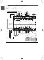
Page 14: ...14 RETURN AIR TEMPERATURE CONTROL PAHCMR000 ENGLISH Electric Wiring Work PAHCMR000 ...

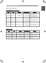
Page 15: ...C x 1 0 1 5 mm2 shield wire Communication with MULTI V Outdoor unit Single IDU Comm SINGLE N SIG Single IDU Comm Max 75 m 2C x 1 0 1 5 mm2 shield wire Communication with Single Split Outdoor unit Name Port Contents Electrical Spec Function Thermistor Room NTC RI1 G Room Return air thermistor NTC 10 kΩ 5 m Return air temperature sensor Thermistor Pipe in NTC RI3 G Pipe in Liquid thermistor NTC 5 kΩ...

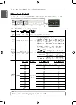
Page 16: ...orced Thermal ON OFF UI3 DI Thermal ON Thermal OFF Non voltage When UI3 Target temp is less than 1 5 V Target temp and Room temp is fixed like below table Target Temp UI4 AI Voltage V Electrical Spec Cooling Mode C Heating Mode C 1 5 DC 0 10 V 20 mA UI3 short 16 C UI3 open 30 C UI3 short 30 C UI3 open 16 C 2 0 16 16 2 5 17 17 3 0 18 18 3 5 19 19 4 0 20 20 4 5 21 21 5 0 22 22 5 5 23 23 6 0 24 24 6 ...

Page 17: ...DI Thermal ON Thermal OFF Non voltage Mode Status Electrical Spec Function UI2 UI3 Cooling Short Open Non voltage Cooling mode operation control Heating Open Short Non voltage Heating mode operation control Fan Open Open Non voltage Fan mode operation control Short Short Non voltage Note DIP SW 1 2 is for contact signal control Mode Cooling mode Heating mode UI4 status Thermal ON Target temp 16 C ...

Page 18: ...ec Function Short Open ON OFF DO1 ON OFF 250 V AC 1 A 30 V DC 1 A Operation ON OFF Status Defrost DO2 Defrost Normal ODU Defrost Status Only total defrost mode Alarm DO3 Error Normal Error output status Name Port Value Electrical Spec Function Short Open Fan_High DO1 High Operation OFF 250 V AC 1 A 30 V DC 1 A The fan will always be running as set fan speed except defrost During defrost the fan sp...

Page 19: ...AC 1 A 30 V DC 1 A DO 1 2 is Open DO 3 Low is short Fan_Mid DO2 TH OFF Fan_Low DO3 TH OFF Heating TH OFF or defrost Name Port Value Electrical Spec Function Short Open Fan_High DO1 TH OFF 250 V AC 1 A 30 V DC 1 A 1 During defrost All DOs are Open 2 The fan speed will be changed according to TH on off In cooling mode The fan speed will be running as low fan during TH off The fan speed will be runni...

Page 20: ...nication with Wired Remote Controller Name Port Item Electrical Spec Function EEV 12 V DC 1 2 3 4 EEV Control Max 5 m EEV Control Name Port Function LD01L LED1 Modbus Comm Tx LD02L LED2 Modbus Comm Rx LD03L LED3 Inner Comm Tx LD04L LED4 Inner Comm Rx LD05L LED5 ODU Comm Repeat ON OFF when communicating with ODU LD06L LED6 Error Status Repeat ON OFF when error occurs Communication Module ...

Page 21: ...nits the outdoor unit is sequentially started at intervals of 10 minutes 4 LG Central Commnunication Type CH3 of Main Module ON Modbus Modbus communication between main module and LG central controller control monitoring possible OFF LGAP AHU LGAP AHU communication between main module and LG central controller monitoring only SW2 1 ODU Capacity Control ON ODU Capacity Setting 2 ODU capacity contro...

Page 22: ...served 2 Reserved 3 4 UI Setting OFF OFF UI Setting 1 Not used OFF ON UI Setting 2 Not used ON OFF ON ON SW3 1 Master Slave ON Slave mode Not used OFF Master mode Master is default 2 3 Operation mode setting OFF OFF Heat Pump Cooling or Heating operation mode is available OFF ON Heating Only Operation mode is Heating only Heating Fan ON OFF Cooling Only Operation mode is Cooling only Cooling Fan O...

Page 23: ...ether 12 V DC or Non voltage for DI Control According to the power supply type of DO please make wirings as below Internal Power Source Non Voltage External Power Source 12 V DC DC 12 V Short Common On Off Cool Heat Emer Stop Common On Off Cool Heat Emer Stop For detail wiring please see Digital Input Internal power source and Digital Input External Power Source 12 V DC in the PDB ...

Page 24: ... DIP SW1 1 is OFF Name Port Value Electrical Spec Function Short Open Fan_Low UI4 Low STOP Non voltage Fan Speed Setting Input Fan_Mid UI5 Mid STOP Non voltage Fan_High UI6 High STOP Non voltage Name Port Value Electrical Spec Function Capacity Control 0 10 V UI7 AI 0 10 V Input DC 0 10 V 20 mA ODU Capacity control input 0 10V When Temp Control Type is Manual by DDC SW 1 2 OFF below UI7 Table sett...

Page 25: ...us A B COM Error Status A B COM Digital Input External Power Source 12 V DC Name Port Value Electrical Spec Function Short Open ON OFF DI1 DCOM ON OFF 12 V DC 10 mA Operation ON OFF Cool Heat DI2 DCOM Heating Cooling 12 V DC 10 mA Operation Mode Emer Stop DI3 DCOM Emergency Stop Normal 12 V DC 10 mA Emergency Stop Input Priority operation DI Control 12 V DCOM Internal Power Source External Power S...

Page 26: ...5 95 0 90 100 10 0 100 0 100 100 1 System 2 System 0 0 Operation OFF 4 0 40 14 0 33 5 4 5 40 14 0 33 5 5 0 50 12 0 36 5 5 5 50 12 0 36 5 6 0 60 10 5 39 0 6 5 60 10 5 39 0 7 0 70 9 0 41 5 7 5 70 9 0 41 5 8 0 80 8 0 44 0 8 5 80 8 0 44 0 9 0 90 7 0 46 5 9 5 90 7 0 46 5 10 0 100 6 0 49 0 Main Module CAUTION The actual temperature at the evaporator may vary by pressure drop Please contact a local sale ...

Page 27: ... ODU Master 4 0 0 0 Operation OFF 2 0 20 0 40 0 40 0 2 5 22 5 50 0 40 0 3 0 25 0 60 0 40 0 3 5 27 5 70 0 40 0 4 0 40 0 40 40 40 40 4 5 47 5 40 50 50 50 5 0 50 0 50 50 50 50 5 5 57 5 50 60 60 60 6 0 60 0 60 60 60 60 6 5 67 5 60 70 70 70 7 0 70 0 70 70 70 70 7 5 77 5 70 80 80 80 8 0 80 0 80 80 80 80 8 5 87 5 80 90 90 90 9 0 90 0 90 90 90 90 9 5 97 5 90 100 100 100 10 0 100 0 100 100 100 100 Voltage ...

Page 28: ... 0 60 10 5 39 0 6 0 50 12 0 36 5 7 0 45 13 0 35 3 8 0 40 14 0 33 5 9 0 Operation OFF 10 0 Operation OFF Main Module CAUTION Actual temperature at evaporator may varies by pressure drop Please contact local sale person to design AHU heat exchanger NOTE Based on 7 5 m piping length condition According to piping length evaporating condensing temperature will be increasing decreasing ODU Capacity rati...

Page 29: ...er Max 50 m Communication with Wired Remote Controller Name Port Item Electrical Spec Function EEV 12 V DC 1 2 3 4 EEV Control Max 5 m EEV Control n NTC Thermistor Name Port Item Electrical Spec Function Thermistor Discharge NTC RI2 G Discharge air Thermistor NTC 10 kΩ 5 m Discharge Air temperature sensor Thermistor Pipe in NTC RI3 G Pipe in Liquid Thermistor NTC 5 kΩ 5 m Inlet pipe Liquid Temp se...

Page 30: ...er or DDC Setting Method Press Set button red Select Addr in 7 Segment using button and then press Set button Press ESC button to exit n Main Module Address Setting Main Module 7 Segment CAUTION Note that LG central controller are using hexadecimal number Please check the address of main module is matching to the address of LG central controller or DDC when using Modbus protocol Otherwise PAHCMS00...

Page 31: ...pe Central Controller Outdoor unit Power Supply Power Supply Indoor unit Indoor unit Fan control Modbus Communication EEV Kit Gas pipe Refrigerant Piping Field Supply Wire Thermistor LG Supply AI DI DO Signal Field Supply Wire Field Supply Air Handling Unit Field supply Local AHU Controller Out of LG scope Wired Remote Controller NOTE The type of power supply of outdoor unit can vary depending on ...

Page 32: ...A1 BUS A BUS B CN_CENTRAL CN_PWR CN_OUT CN_CP N CN_CP L 2 N 1 L 3 CN_COM L N Power Supply Power Supply L N L N B CH1 A CH1 Modbus Communication Adapter Refrigerant Piping Field Supply Wire Thermistor LG Supply AI DI DO Signal Field Supply Wire Field Supply Air Handling Unit Field supply Local AHU Controller Out of LG scope Wired Remote Controller NOTE The type of power supply of outdoor unit can v...

Page 33: ...B GND 12V SIG A B CH2 Comm module EEV Adapter L N B CH4 A CH4 Modbus Communication A B CH3 Central Controller A B ACP CH5 AC SMART CH1 Gas pipe EEV Kit Refrigerant Piping Field Supply Wire Thermistor LG Supply AI DI DO Signal Field Supply Wire Field Supply Air Handling Unit Field supply Local AHU Controller Out of LG scope Wired Remote Controller NOTE The type of power supply of outdoor unit can v...

Page 34: ...N_CENTRAL CN_PWR CN_OUT CN_CP N CN_CP L L N Power Supply Adap ter L N B CH4 A CH4 A B CH3 A B ACP CH5 AC SMART CH1 Central Controller Modbus Communication Refrigerant Piping Field Supply Wire Thermistor LG Supply AI DI DO Signal Field Supply Wire Field Supply Air Handling Unit Field supply Local AHU Controller Out of LG scope Wired Remote Controller NOTE The type of power supply of outdoor unit ca...

Page 35: ...lfunctionCode_XX AI 0 255 Refer to the LG Error code list 13 Set Temperature Status ac_SetTempStatus_XX AI C 16 30 C 14 Set Upper Temperature Setting ac_TempRangeUpperLimitCommand_XX AV C 16 30 C 15 Set Lower Temperature Setting ac_TempRangeLowerLimitCommand_XX AV C 16 30 C 16 Set Upper Temperature Status ac_TempRangeUpperLimitStatus_XX AI C 16 30 C 17 Set Lower Temperature Status ac_TempRangeLowe...

Page 36: ...ctionTemp_XX AI C 7 Liquid Pipe Temperature outdoor_LiquidPipeTemp_XX AI C 8 Heat Exchanger Temperature outdoor_HexTemp_XX AI C 9 Outdoor EEV outdoor_OutdoorEEV_XX AI 10 Subcool EEV outdoor_SubCoolEEV_XX AI 11 Hot Gas Valve outdoor_HotgasValue_XX BI Stop 0 Run 1 12 Inverter Discharge Temperature outdoor_InverterDischargeTemp_XX AI C 13 Outdoor Temperature outdoor_OutdoorTemp_XX AI C 14 Operation M...

Page 37: ...100 0 1 ON 12 Mode Lock Status SNVT_switch nvoModlok output 0 0 0 OFF 100 0 1 ON 13 Fan Speed Lock Setting SNVT_switch nviFanlok input 0 0 0 OFF 100 0 1 ON 14 Fan Speed Lock Status SNVT_switch nvoFanlok output 0 0 0 OFF 100 0 1 ON 15 Temperature Lock Setting SNVT_switch nviTmplok_Humid input 0 0 0 OFF 100 0 1 ON 16 Temperature Lock Status SNVT_switch nvoTmplok_Humid output 0 0 0 OFF 100 0 1 ON 17 ...

Page 38: ...eserved 10001 Comp Status 0 OFF 1 ON 10002 Defrost Status 0 Normal 1 Defrost 10003 Oil Return 0 Normal 1 Oil Return 10004 Reserved 10005 Reserved 10006 Reserved 10007 Reserved 10008 Reserved 30001 Error Code 0 255 30002 RA Temp 50 0 C 100 0 C x10 30003 Reserved 30004 Pipe In Temp 50 0 C 100 0 C x10 30005 Pipe Out Temp 50 0 C 100 0 C x10 30006 Capacity 0 255 kBtu 30007 Reserved 30008 Reserved 40001...

Page 39: ...us 0 Normal 1 Defrost 10014 ODU 1 Error Status 0 Normal 1 Error 10015 ODU 2 Operation Status 0 OFF 1 ON 10016 ODU 2 Comp Status 0 OFF 1 ON 10017 ODU 2 Defrost Status 0 Normal 1 Defrost 10018 ODU 2 Error Status 0 Normal 1 Error 10019 ODU 3 Operation Status 0 OFF 1 ON 10020 ODU 3 Comp Status 0 OFF 1 ON 10021 ODU 3 Defrost Status 0 Normal 1 Defrost 10022 ODU 3 Error Status 0 Normal 1 Error 10023 ODU ...

Page 40: ...Reserved 30013 SA Temp 50 0 C 100 0 C x10 30014 Reserved 30015 Reserved 30016 Reserved 40001 Operation Mode 0 Cooling 2 Fan 4 Heating 40002 Capacity 1 0 2 0V 10V x10 0 5V 40003 Cooling Target Temp 16 0 C 30 0 C x10 1 C 40004 Heating Target Temp 16 0 C 30 0 C x10 1 C 40005 Reserved 40006 Reserved 40007 Reserved 40008 Reserved 40009 Reserved 40010 Reserved 40028 Fan Speed 1 Low 2 Middle 3 High Memor...

Page 41: ...eration If you want to turn off the fan during TH off or defrost or control by fan speed please refer to DIP switch setting SW1 3 SW1 4 of Comm module CONNECTION SETTING GUIDE Fan Alarm interlock guide 1 Return air temperature controller If DO Type setting SW 1 3 set as Status fan operating signal can be interfaced with operation status signal at DO 1 in DIGITAL OUTPUT ...

Page 42: ...ure controller Fan operating signal can be interfaced with operation status signal at DO 2 in DIGITAL OUTPUT of main module NOTE The fan is kept ON during operation If you want to control the fan according to defrost status and fan speed please interlock defrost signal output Main Module Main Module DO 3 and fan speed signal output Communication module DO 1 3 ...

Page 43: ...d AHU controller All PAHCMR000 units need to be set as Master mode Once Main module is turned on It finds ODU from the ODU address 00 01 02 03 and finds Communication module from the IDU central controller address 00 01 02 03 and finds EEV module and then indicates total number of module Comm module EEV module Address setting guide Remote controller Central control No Contents Address setting Note...

Page 44: ...iring A B C AHU controller Detail AHU EEV controller WARNING Please connect one controller with one terminal block of EEV Kit Failure to do so may result in component damage or fire Refer to correct wiring Incorrect wiring AHU controller WARNING Do not connect to the AHU Controller directly after wiring two terminal blocks together inside of the EEV Kit A Terminal box cover B Electrical connection...

Page 45: ...OR BL RD BD D D WH YL OR BL RD NTC Note BR Brown RD Red BL Blue OR Orange YL Yellow WH White Field Wiring WARNING Before installation check the color on the label and connect it to the terminal block It may result in malfunction Use a ring type terminal P4 to connect to the terminal block B Electrical connection 1 C Electrical connection 2 AHU Controller AHU EEV Controller ...

Page 46: ...46 ENGLISH ...

Page 47: ......

Reviews: