background image

38

MultiSITE CRC 2 Controller

Due to our policy of continuous product innovation, some specifications may change without notification.  

©LG Electronics U.S.A., Inc., Englewood Cliffs, NJ. All rights reserved. “LG” is a registered trademark of LG Corp.

ACCESSORIES INSTALLATION

CO

2

, Temperature, and Humidity Sensor  

SEDCO2G5045 / Temperature and Humidity Sensor 

ZVRCZTRH1

Follow this procedure to install the optional SEDCO2G5045 and ZVRCZTRH1  

sensors.
Consider the following location constraints before installing a ceiling/wall sensor:

• 

 Do not install a on metal surface.

• 

 Do not install in areas with a direct heat source.

• 

 Do not install near any air discharge grill.

• 

 Do not install in areas exposed to direct sunlight.

• 

Ensure mounting surface is flat and clean. 

•  Install in a dry location away from water, moisture, or rain.

Sensor Installation

The wireless CO2 + TRH / TRH sensors can be secured directly on a wall or flat 

surface using double-sided adhesive tape  or by securing the plastic bracket to the 

wall and mounting the sensor. Using the screws is the recommended method.
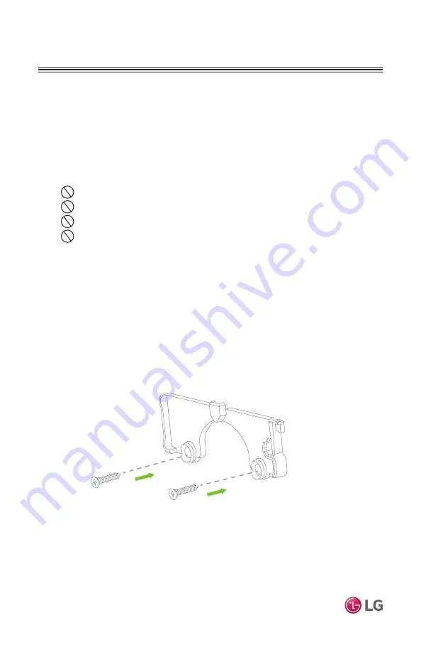
1.  Using two screws provided, secure wall bracket to wall (Figure 41).

2.  Once bracket is secured, slide sensor on bracket using downward motion. 

Figure 41: Wall Bracket Installation

Summary of Contents for MultiSITE CRC2 Series

Page 1: ...llers INSTALLATION MANUAL PREMTBVC2 MultiSITE CRC2 PREMTBVC3 MultiSITE CRC2 PREMTBVC4 MultiSITE CRC2 Z with Zigbee Onboard 05 16 2021 2 43 PM Occ Auto Heat 74 78 Indoor F Humidity 66 68 Auto Locked by central controller CO2 526ppm ...

Page 2: ...nd operation For more technical materials such as submittals engineering databooks and catalogs visit www lghvac com For continual product development LG Electronics U S A Inc reserves the right to change specifications without notice LG Electronics U S A Inc This document as well as all reports illustrations data information and other materials are the property of LG Electronics U S A Inc PROPRIE...

Page 3: ...sories Installation 17 ZigBee Pro and Wi Fi Wireless Modules 17 Ceiling Motion Sensor Old Model ZVRCZCOC1 19 Wall Mounted Motion Sensor 22 Door Window Sensor Old Model ZVRCZDWS1 25 Door Window Sensor ZVRCZDWC1 29 Ceiling Wall Motion Temperature and Humidity Sensor ZVRCZMTH1 32 Water Leak Sensor ZVRCZWLS1 35 CO2 Temperature and Humidity Sensor SEDCO2G5045 38 ZigBee Setup 42 ZigBee Pro Quick Setup 4...

Page 4: ...his symbol indicates an imminently hazardous situation which if not avoided will result in death or serious injury WARNING This symbol indicates a potentially hazardous situation which if not avoided could result in death or serious injury CAUTION This symbol indicates a potentially hazardous situation which if not avoided may result in minor or moderate injury This symbol indicates situations tha...

Page 5: ...ction devices If the pressure switch thermal switch or other protection device is shorted and forced to operate improperly or parts other than those specified by LG are used there is risk of fire electric shock explosion and physical injury and or death If the air conditioner is installed in a small space take measures to prevent the refrigerant concentration from exceeding safety limits in the ev...

Page 6: ... panel Do not allow water dirt or animals to enter the unit There is risk of unit failure or degraded performance Do not spill water or other liquid on the inside of the indoor unit espe cially on electrical components Do not drop the MultiSITE Controller unit into water If the unit is im mersed in water or other liquid contact your local authorized LG distributor for support There is risk of unit...

Page 7: ...ories These accessories are available for MultiSITE CRC2 controllers ZigBee Pro wireless card Model ZVRCZPWC2 Door and window switch Model ZVRCZDWC1 Wall mounted occupancy sensor Model ZVRCZWOC1 Ceiling mounted occupancy temperature humidity sensor Model ZVRCZMTH1 Temperature humidity sensor Model ZVRCZTRH1 CO2 Temperature humidity sensor Model SEDCO2G5045 Water leak sensor Model ZVRCZWLS1 WiFi ca...

Page 8: ... Mode Status Current Fan Speed Setting Up Arrow Raise Temperature Setpoint Room Indoor Temperature Down Arrow Lower Tempera ture Setpoint On Off Turn the display on or off Schedule Set weekly schedule More Provides user with access to less often used functions Fan Speed Set fan to Slow Low Low Med Medium Med High High Power Auto Available options depend on IDU model Operation Mode Set Cool Heat Au...

Page 9: ...f hot or cold air Install the controller on a flat clean wall surface approximately 5 ft above the floor in an area with good circulation and average temperature Do not install the controller where it is exposed to Drafts or dead spots behind doors and in corners Hot or cold air from ducts Radiant heat from sun or appliances Concealed pipes or chimneys Uncontrolled areas such as on an outside wall...

Page 10: ...ed The PREMTBVC3 and PREMTBVC4 contain a passive infrared PIR sensor Refer to Figure 2 for onboard PIR sensor information to consider when selecting the PREMTBVC3 or PREMTBVC4 installation location Figure 2 Onboard Motion PIR Sensor Installation 20 O 20 O 20 O 20 O 40 O A B B C C Horizontal Angles Typical Transverse motion 4 5 ft s 1 5 m s Recommended installation height for PIR sensor 4 5 ft 1 2 ...

Page 11: ...tions Maximum cable length is 164ft Do not splice wiring Cable Type 3 conductor 22 AWG unshielded twisted and stranded If the indoor unit does not have screw terminals for field wiring Extension Cable PZCWRC1 is required The green Molex connector of this cable connects to the IDU The white Molex connector of this cable is removed and the wires connected to the Remote Controller as described below ...

Page 12: ...Common Not used Not used Not used Common 4 5 6 13 14 15 Typical Indoor Unit Signal 12VDC YL RD BK CONTROLLER INSTALLATION Installing the Controller continued 8 Insert screws in mounting holes on each side of base 9 If using field provided com munication cable strip each wire 1 4 inch from end 10 If using Extension Cable PZCWRC1 carefully cut off the white Molex connector and strip each wire 1 4 in...

Page 13: ...ock ac cording to wiring diagram Figure 5 Table 1 lists the function of all terminal connections 12 Carefully push excess cable back into hole 13 Gently align cover to top of base and snap in place from bottom Figure 6 14 Install security screw Terminal Function Terminal 1 Not used Terminal 2 Not used Terminal 3 Not used Terminal 4 Signal Wire Terminal 5 12VDC Terminal 6 Common Terminal 13 BACnet ...

Page 14: ...ked by central controller CO2 526ppm Touch and hold this point for 3 seconds to enter setup mode If a configuration installer pass word is activated to prevent unau thorized access to the configuration menu parameters a password entry prompt will appear to prevent access to the device configuration components CONTROLLER SETUP Controller Setup This section contains a brief overview of MultiSITE con...

Page 15: ...peration In Cooling mode the setpoint displayed in the bar is the current occupied cooling setpoint During occupied setpoint adjustment the large digits are temporarily used to display the occupied cooling setpoint while it is adjusted Normal temperature display resumes after the setpoint is adjusted and the actual occupied cooling setpoint is displayed in the setpoint bar Heating mode or heating ...

Page 16: ...lay the occupied Cooling Setpoint or occupied Heating Setpoint The actual setpoint is dependent on the last effective demand heating or cooling The CRC setpoint adjustment defaults to cooling adjustment first regardless of the current mode To switch to heating setpoint adjustment tap either the up or down arrow Cooling Setpoint will appear on the screen Immediately tap the Mode button to switch to...

Page 17: ...i Fi module is required for BACnet over IP ACCESSORIES INSTALLATION Figure 8 ZigBee Pro and Wi Fi Wireless Modules 1 Remove security screw if any on bottom of Remote Controller cover 2 Open unit by pulling on bottom side of Remote Controller Figure 9 3 Carefully remove Remote Control ler s Motherboard from casing and turn over 4 Locate gap in upper right corner of Remote Controller s motherboard a...

Page 18: ...ES INSTALLATION Figure 10 Install ZigBee Pro or Wi Fi Wireless Module Figure 11 Reinstall Cover 6 Gently press the ZigBee Pro or Wi Fi module into the Remote Controller s motherboard until it fits snugly in place Do not press too hard to avoid damage to ZigBee Pro or Wi Fi module 7 Carefully replace Remote Controller s motherboard into casing 8 Carefully align cover to top of base and snap in plac...

Page 19: ...fore installing a ceiling mounted sensor Do not install on a metal surface Do not install in areas with a direct heat source Do not install near any air discharge grill Do not install in areas exposed to direct sunlight Ensure ceiling surface is flat and clean Install in a dry location away from water moisture or rain Sensor Placement Figure 13 shows suggested placement guidelines to optimize dete...

Page 20: ...ting housing counter clockwise Figure 14 2 Install two AAA batteries in Sensor Housing Figure 15 Ensure battery polarity is correct When batteries are first installed the sensor automatically goes into pairing mode Refer to ZigBee Setup on page 42 3 Replace mounting plate by rotating housing clockwise 4 Proceed to Verify Sensing Motion Verify Sensing Motion 1 Wait three minutes for sensor to warm ...

Page 21: ...que screws 3 Set sensor housing assembly on mounting plate Figure 17 4 Rotate sensor housing assem bly clockwise until it locks in place Ensure sensor housing assembly fits snugly to mount ing plate 5 Test the ceiling motion sensor again according to Verify Sensing Motion on page 20 Sensor Functions Figure 18 shows the location of the function button on the sensor module Refer to Table 2 Function ...

Page 22: ...or Consider the following location constraints before installing a wall mounted sensor Do not install on a metal surface Do not install in areas with a direct heat source Do not install near any air discharge grill Do not install in areas exposed to direct sunlight Ensure wall surface is flat and clean Install in a dry location away from water moisture or rain Sensor Placement Figure 20 shows sugg...

Page 23: ...ewdriver to carefully pry cover away from motion sensor Figure 21 2 Install one CR2 battery in Sensor Housing Figure 22 Ensure bat tery polarity is correct When bat tery is first installed the sensor automatically goes into pairing mode Refer to ZigBee Setup on page 42 3 Replace cover on motion sensor 4 Proceed to Verify Sensing Motion Verify Sensing Motion 1 Wait three minutes for sensor to warm ...

Page 24: ...o Sensor Placement on page 22 2 Affix two sided tape to desired installation location Figure 24 3 Position motion sensor on two sided tape and press firmly to secure in place 4 Test the wall mounted motion sensor again according to Verify Sensing Motion on page 23 Sensor Functions Figure 25 shows the location of the function button on the sen sor module Refer to Table 2 Function Button and LED Ind...

Page 25: ...l surface Do not install in areas with a direct heat source Do not install near any air discharge grill Do not install in areas exposed to direct sunlight Ensure mounting surface is flat and clean Install in a dry location away from water moisture or rain Sensor Placement Figure 27 shows suggested placement guidelines to optimize sensor operation En sure contact switch and magnet face each other a...

Page 26: ...nstall one CR2032 battery in the housing Figure 29 Ensure battery polarity is correct When battery is first installed the sensor automatically goes into pairing mode Refer to ZigBee Setup on page 42 3 If replacing an old battery use a plastic tool to carefully pry battery out of compartment Do not use a metal tool it may cause a short circuit or cause damage to the sensor 4 Replace housing cover I...

Page 27: ...Slide the sensor into the housing Install Magnet Use either screws or two sided tape to install the magnet The sensor housing and the magnet must align properly The sensor and magnet must be within 0 75 inches of each other Be sure to install the parts in the correct orientation If installing with tape the magnet s screw tab can be removed by snapping the tab along the scored line Figure 32 To ins...

Page 28: ...tions Figure 33 shows the location of the function button on the sensor module Refer to Table 2 Function Button and LED Indicators on page 43 for information on using this button and the LED indicator to set up sensor module operation ACCESSORIES INSTALLATION Figure 32 Remove Screw Tab if Desired Figure 33 Function Button and LED Test Sensor with Controller Refer to ZigBee Pro Quick Setup on page ...

Page 29: ...g location constraints before installing a door window sensor Do not install a on metal surface Do not install in areas with a direct heat source Do not install near any air discharge grill Do not install in areas exposed to direct sunlight Ensure mounting surface is flat and clean Install in a dry location away from water moisture or rain Sensor Placement Figure 35 shows suggested placement guide...

Page 30: ... the window door frame and the sub magnet part on the window door itself The sub part must be installed so that it is located on the sensing side of the main part when the window door is closed The main part base plate has arrow indicators to help with alignment and posi tioning Recommended distance from main part to sub part when window door is closed Wood 11 16 inch Plastic 11 16 inch Metal 3 8 ...

Page 31: ... to put the remote controller into pairing mode 2 Short press the function key 3 times within 1 second 3 The sensor pairs with the controller Resetting the sensor 1 Short press the function key 3 times within 1 second 2 Press and hold the function key until the status LED indicates factory reset mode approximately 10 seconds 3 Release the function key 4 The sensor restarts Checking the sensor stat...

Page 32: ... sensor Consider the following location constraints before installing a ceiling wall sensor Do not install a on metal surface Do not install in areas with a direct heat source Do not install near any air discharge grill Do not install in areas exposed to direct sunlight Ensure mounting surface is flat and clean Install in a dry location away from water moisture or rain Sensor Placement Figure 37 s...

Page 33: ... base plate is attached to the wall with the TOP arrow up For wood or plastic surfaces use either the adhesive pads or the mounting screws If using screws pre drill a 1 32 in hole For metal surfaces use the adhesive pads only For ceiling mounting using screws is recommended 3 Attach the sensor to the base plate Insert the hooks on the base plate into the slots on the sensor Turn the sensor body cl...

Page 34: ...ntroller into pairing mode 2 Short press the function key 3 times within 1 second 3 The sensor pairs with the controller Resetting the sensor 1 Short press the function key 3 times within 1 second 2 Press and hold the function key until the status LED indicates factory reset mode approximately 10 seconds 3 Release the function key 4 The sensor restarts Checking the sensor status 1 Short press the ...

Page 35: ... optional water leak sensor Consider the following location constraints before installing a ceiling wall sensor Do not install a on metal surface Do not install in areas with a direct heat source Do not install near any air discharge grill Do not install in areas exposed to direct sunlight Ensure mounting surface is flat and clean Install in a dry location away from water moisture or rain Sensor P...

Page 36: ...n where water leakage will be detected soon after the leak starts For example At the side of a bath tub or vanity unit to detect overflow from the tub or sink Beneath a hot water radiator control tap Near a water pipe or tap to detect leakage 2 Ensure that the sensor is placed so that the sensing pads are in contact with the floor 3 Avoid locations where the sensor may be accidentally kicked or ot...

Page 37: ...iring mode 2 Short press the function key 3 times within 1 second 3 The sensor pairs with the controller Resetting the sensor 1 Short press the function key 3 times within 1 second 2 Press and hold the function key until the status LED indicates factory reset mode approximately 10 seconds 3 Release the function key 4 The sensor restarts Checking the sensor status 1 Short press the function key 3 t...

Page 38: ... sensor Do not install a on metal surface Do not install in areas with a direct heat source Do not install near any air discharge grill Do not install in areas exposed to direct sunlight Ensure mounting surface is flat and clean Install in a dry location away from water moisture or rain Sensor Installation The wireless CO2 TRH TRH sensors can be secured directly on a wall or flat surface using dou...

Page 39: ...to attach the sensor to the wall by using the two screws The adhesive in double sided tape may not be as long lasting or as strong to sup port the sensor throughout its lifetime Figure 42 shows where to attach the tape Double sided adhesive tape zone Figure 42 Double Sided Tape Installation 3 Ensure click sound is heard to verify sensor is secured to bracket and ensure side tab of bracket is align...

Page 40: ...or is in the decommis sioned energy saving hibernation mode If the sensor is already commissioned it will enter demo mode for a 5 minute timeout interval Long push One long push puts the sensor into decommissioned hibernate mode The long push is confirmed by one red LED flash roughly 1 second after 2 yellow LED push signaling flashes After a red LED signal the button should be released in order to...

Page 41: ... hap pen automatically using the built in auto calibration function This technique can be used in situations in which sensors will be exposed to typical background levels 400 450ppm at least once during the autocalibration period For example many buildings will drop quickly to background CO2 levels when unoccupied overnight or on weekends The autocalibration function uses the information gathered ...

Page 42: ...e Ecosystem section of MultiSITE CRC2 Series Remote Controller s interface and set Permit join to On Permit join is only available on the first Zone Screen but is applicable to all Zones 2 Insert battery Remove pull tab for contact sensors or press button for sensors without pull tab to activate ZigBee sensor If sensor does not join ZigBee wireless network press the button located on the sensor te...

Page 43: ...eck Pairing G x5 Paired 3x 1 s 10s Rese ng R 1 s R G x7 See Ac on N A N A Y 1 min Low Ba ery 1x 1 s Pairing Y x2 G x3 Pairing 1x for 3 s Rese ng Y x2 R x1 release a er 1st red Unpair G x3 Joined R x3 Not Joined Y x3 Re join in Process Y R Y Searching for Network Y G Y Device Being Configured G x3 Device Joined R x3 Device Failed to Join 8x 1 s Forced Re join Y x3 Re join Searching for Parent R x3 L...

Page 44: ...Config BACnet settings menu of the Configuration page 3 Change the COM Address Valid COM address range is 0 253 Note COM address defaults to 254 which disables BACnet MS TP 4 Select Network Units Imperial or Metric 5 Select appropriate BAUD Rate Note Auto is the default setting and will auto detect baud rate of connected device 6 Select BACnet Instance Number or use default BACnet Instance Note BA...

Page 45: ...ng Storage Conditions 22 F 122 F 0 95 R H non condensing Temperature Sensor Local 10 K NTC type 2 thermistor Temperature Sensor Resolution 0 2 F Temperature Control Accuracy 0 9 F 70 F typical calibrated Humidity Sensor and Calibration Single point calibrated bulk polymer type sensor Humidity Sensor Precision Reading range from 10 90 R H non condensing 10 to 20 precision 10 20 to 80 precision 5 80...

Page 46: ...B ICES 003 Radio Standards Wireless Models R TTE Directive 1999 5 EC IEC 61326 1 2005 EN 301 489 1 V1 9 2 EN 301 328 V1 8 1 FCC 15 Subpart C RSS 210 THIS DEVICE COMPLIES WITH PART 15 OF THE FCC RULES OPERATION IS SUBJECT TO THE FOLLOWING TWO CONDITIONS 1 THIS DEVICE MAY NOT CAUSE HARMFUL INTERFERENCE AND 2 THIS DEVICE MUST ACCEPT ANY INTERFERENCE RECEIVED INCLUDING INTERFERENCE THAT MAY CAUSE UNDE...

Page 47: ... radio commu nications Operation of this equipment in a residential area is likely to cause harmful interference in which case the user will be required to correct the interference at his own expense This device complies with part 15 of the FCC Rules Operation is subject to the following two conditions 1 This device may not cause harmful interference and 2 This device must accept any interference ...

Page 48: ...some specifications may change without notification LG Electronics U S A Inc Englewood Cliffs NJ All rights reserved LG is a registered trademark of LG Corp LG Customer Information Center Commercial Products 1 888 865 3026 USA Follow the prompts for commercial A C products and parts ...

Page 49: ......

Page 50: ...12_21 Supercedes IM_CRC2_Series_Controllers_11_21 IM_CRC2_Series_Controllers_9_21 IM_CRC2_Series_Controllers_7_21 LG Electronics Commercial Air Conditioning Division 4300 Northpoint Parkway Alpharetta Georgia 30022 www lghvac com ...

Reviews: