65
Final Installation Procedures
Due to our policy of continuous product innovation, some specifications may change without notification.
©LG Electronics U.S.A., Inc., Englewood Cliffs, NJ. All rights reserved. “LG” is a registered trademark of LG Corp.
FINAL INSTALLATION PROCEDURES
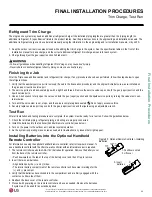
Finishing the Job
After the Triple Leak and Evacuation (and refrigerant trim charge, if any) procedures have been performed, follow the steps below to open
the refrigerant lines.
1. Verify that the auxiliary service port is removed (if used in the Evacuation procedure) and the original Schrader core was re-installed on
the gas (vapor) suction service port.
2. The service ports are a back-seated type with a right hand thread. Remove the service valve caps on both the gas (vapor) suction and the
liquid service ports.
3. Use an Allen wrench to fully open the valves on both the gas (vapor) suction and the liquid service ports by turning the valve stem coun-
terclockwise.
4. Turn until the valve stem is out, stops, and the valve is completely backseated.
Do not apply excessive force.
5. Securely replace service port caps on both the gas (vapor) suction and the liquid using an adjustable wrench.
Test Run
After all installation and testing procedures are complete, the system must be ready for a test run. Follow the guidelines below.
1. Check that all drain piping, refrigerant piping, and wiring are properly connected.
2. Install the batteries into the (optional) handheld remote controller (see below).
3. Turn on the power to the outdoor unit, and test system operation.
4. As the system is operating, make notes as needed to troubleshoot any issues that might appear.
Installing Batteries into the Optional Handheld
Remote Controller
For information on using the optional handheld remote controller, refer to its owner’s manual. To
use a handheld controller with the VAHU, a wall controller with an infrared receiver is required.
1. The remote controller needs two AAA (1.5V) batteries for operation. Remove the battery cover
from the back of the remote controller.
• Push downward on the tab at the top of the battery cover and then lift up to remove.
2. Insert the two new batteries.
• Align batteries by the (+) and (-) sides.
• The interior battery compartment of the remote controller will have clear markings for the
(+) and (-) placement.
3. Verify that the batteries have clicked into the compartment and are firmly engaged with the
contacts on either side of them.
4. Reattach the back cover of the remote controller.
5. Proceed with powering on the remote controller and use as needed. Remove the batteries
if system won’t be used for an extended period.
1. Push down on tab
2. Lift cover
3. Insert
3
batteries
Single Zone Remote Controller - Rear View
Battery Cover
Tab
Battery
Cover
Figure 85: Optional Remote Controller - Installing
Batteries
Refrigerant Trim Charge
The single zone system may need an additional refrigerant charge if the installed piping lengths are greater than the “piping length (no
additional refrigerant, ft.) specification” listed in the product tables. See the product sections in the engineering and installation manuals. The
additional refrigerant charge can be calculated manually using the information in the engineering and /or installation manuals, or by LATS.
1. Keep the outdoor unit service values closed while adding the trim charge to the system. See the specification tables in the front of this
installation manual for base charge, and the correct additional refrigerant trim charge amounts for each system.
2. Charge through just the gas (vapor) suction Schrader port.
• Follow all guidelines when handling refrigerant. Not doing so may cause bodily injury.
• Never inhale or handle refrigerant directly. Doing so may cause bodily injury.
Trim Charge, Test Run
Summary of Contents for LV181HV4
Page 73: ...NOTES ...


