24
Single Zone V
ertical
Air Handling Unit Installation Manual
Due to our policy of continuous product innovation, some specifications may change without notification.
©LG Electronics U.S.A., Inc., Englewood Cliffs, NJ. All rights reserved. “LG” is a registered trademark of LG Corp.
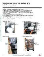
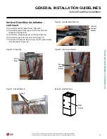
6. Install the conversion kit left and right rear vertical brackets in the rear corners of the cabinet (Figure 20).
7. Position the rear horizontal bracket on the two vertical brackets and secure with screws (Figure 21).
8. Position the left and right horizontal side brackets and secure with screws (Figure 21). The brackets are not
left/right hand dependent.
9. Position the front horizontal bracket and secure with screws (Figure 21).
10. Confirm all bracket screws are secure and the bracket assembly is correctly positioned to support the evap-
orator coil/drain pan assembly.
11. Route the wiring for the pipe in and pipe out sensors (Figure 22).
12. Carefully slide the evaporator coil/drain pan assembly back into the cabinet (Figure 23). Confirm the assem-
bly is against the rear panel of the cabinet.
Figure 20: Vertical Brackets.
Vertical
Bracket
Rear
Bracket
Side
Brackets
Front
Bracket
Figure 21: Horizontal Brackets.
Figure 22: Route Wiring.
Sensor
Wiring
Figure 23: Reinstall Coil Assembly.
Evaporator
Coil/Drain
Pan Assembly
Vertical Downflow Installation - continued
Vertical Downflow Installation
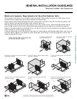
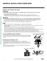
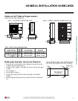
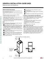
GENERAL INSTALLATION GUIDELINES
Summary of Contents for LV181HV4
Page 73: ...NOTES ...

