


60
Single Zone V
ertical
Air Handling Unit Installation Manual
Due to our policy of continuous product innovation, some specifications may change without notification.
©LG Electronics U.S.A., Inc., Englewood Cliffs, NJ. All rights reserved. “LG” is a registered trademark of LG Corp.
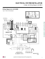
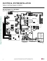
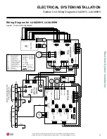
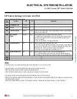
ELECTRICAL SYSTEM INSTALLATION
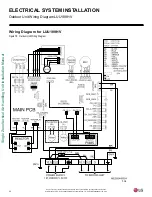
NJ, NK Wiring Diagrams Legend
Table 19: NJ/NK Frame Wiring Diagram Legend.
Terminal
Purpose
Function
CN-POWER
AC Power supply
AC Power line
CN-MOTOR1
Fan motor output
Motor output of BLDC
CN_OUT
Heater
Connection for heater
CN-D/PUMP
Drain pump output
AC output for drain pump
CN-FLOAT
Float switch input
Float switch sensing
CN-ZONE
Zone controller
Zone controller connection
CN-OPTION
Optional PCB EPROM
Option PCB connection
CN-EXT
External ON / OFF controller
External ON / OFF controller connection
CN-DISPLAY
Display
Display of indoor status
CN-CC
Dry contact
Dry Contact connection
CN-PIPE/OUT (RD)
Discharge pipe sensor
Pipe out thermistor
CN-LEAK (VI)
Refrigerant leak detector
Refrigerant leak detector connection
CN-PIPE/IN (WH)
Suction pipe sensor
Pipe in thermistor
CN-REMO (GN)
Wired remote controller
Wired remote control connection
CN-ROOM (YL)
Room sensor
Room air thermistor
CN-DAMPER
Damper Controller
Damper connection
CN-AIRC
Air Cleaner
Air Cleaner connection
CN-WF
Wifi
Wifi Module connection
CN-PTC
Auxiliary Heater Relay Kit
Auxiliary Heater Relay Kit
Second stage heat
Summary of Contents for LV181HV4
Page 73: ...NOTES ...


