background image

47

TROUBLESHOOTING

No

Result & SVC Action

Checking flow

(1) to (2)

1500~1700

Other

Explain

Replace Water

valve

SVC Action

Result

1

2

3

4

Check the Red to  Blue.
(While pushing the lever S/W)

Check the Pin25 to  Pin26 of CON7.
(While pushing the lever S/W)

Check the resistance value.

CON 3

Check the loose connection.

3. Troubleshooting Without Error Display

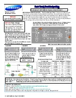
16) Water mode doesn’t work

Pushing

Not pushing

100~127V

Other

0~2V

Other

Go to the 3

Change PCB

Go to the 3

Change PCB

SVC Action

Result

Lever s/w

Point

Lever s/w

Pushing

Not pushing

4.5~5V

Other

0~2V

Other

Go to the 4

Change PCB

Go to the 4

Change PCB

SVC Action

Result

Summary of Contents for LSSB2691ST

Page 1: ...LSSB2691ST REFRIGERATOR SERVICE MANUAL ...

Page 2: ...rror Codes 29 Chapter 9 How to Disassemble and Assemble 55 1 Top Cover 55 2 1 Top Decor 55 2 2 Machine Cover 55 2 3 Case Decor 55 2 4 PCB Cover 55 3 F Door 56 3 1 F Door adjustment top and bottom 57 3 2 F Door adjustment right and left 57 4 R Door 57 4 1 R Door adjustment top and bottom 57 4 2 R Door adjustment of level difference of right and left 58 4 3 Door hinge damper 58 5 HANDLE 59 6 1 DISPE...

Page 3: ... injury if the instructions are not followed Be cautious of electric shock Control board PWB Main and Sub uses power supply of about 120 VAC Be sure the plug and cord are not pressed by the rear side of the refrigerator Damage to power plugs could result in fire or electric shock Plug the refrigerator into a dedicated circuit Plugging in too many appliances can result in fire or problems with the ...

Page 4: ...a or similar items The refrigerator is for storing food This is a consumer household appliance and not a precision device If storing or disposing of the refrigerator remove the doors to eliminate the possibility of children playing in it Children may become entrapped in the refrigerator Unplug the refrigerator for cleaning or repair Be sure your hands are dry when handling the power cord or plug E...

Page 5: ...not install the refrigerator next to a stove or other sources of heat There is danger of fire When a gas leak occurs do not unplug the refrigerator Open the doors for ventilation There is danger of burning due to explosion and sparking Do not clean the refrigerator by spraying water inside or outside It may result in product damage fire or electric shock This refrigerator is designed for use as a ...

Page 6: ...tions free from dust and contamination There is danger of fire from shorting or arcing Be sure replacement parts are an exact fit Replacement parts should look and fit exactly like the original parts and have the same electric rating Do not let moisture drop onto electrical parts If there is a problem in this area replace the parts or tape the wires to prevent contamination and degradation If you ...

Page 7: ...tion the doors and icemaker may not operate properly Do not install the refrigerator in a place where it is subject to splashing and excess moisture Deterioration of insulation may cause electrical leakage Do not touch foods containers or the inside of the freezer compartment with wet hands Your hands may stick to the cold items It could cause frost bite Be careful to avoid pinching hands or feet ...

Page 8: ...tion Capillary tube Product related parts Parts consens ation with dewing prevention For preventing ice making For controlling the temperature in Magic Room Freezer Refrigerator Initial defrost Defrost cycle Rest time Defrost sensor Temp fuse rated operation temperature Heater sheath Dispenser duct door heater Dispenser heater Refrigerator home bar heater Freezer home bar heater Water supply heate...

Page 9: ...9 Circuit Diagram Chapter 3 Circuit Diagram ...

Page 10: ...e C Case including back handle D After disassembling door including hinge L E Including door not including handle F Including handle G When opening door by 90 H At rear I From Floor to Front Pannel J Top part Side Rear part 41 1041 42 1067 45 1143 22 1 2 572 25 1 2 649 25 3 8 645 27 1 2 698 5 48 1 3 1228 83 1 4 2114 82 1 2 2098 1 4 6 1 4 6 1 6 4 Unit inch mm Front View Top View ...

Page 11: ...fications 2 Parts Automatic Icemaker Freezer Compartment Refrigerator Compartment Door Rack 2 Drawer 3 Drawer 3 Lower Cover Shelf 8 Top Cover LED Function displayboard Moving Basket 3 Dairy Corner Gallon Basket ...

Page 12: ...e like vacation Lock State Indicator shows the current status for the control panel functions is set to LOCK Dispenser selection indicator Shows water cubed ice or crushed Ice selection that will be dispensed when the push switch is pressed 1 2 Display Second Function 1 Alarm mute Mode When the power of the refrigerator is turned on for the first time the buzzer icon lights up and when the door is...

Page 13: ... F 42 8 F 45 5 F 2nd press 3rd press 4th press 5th press 6th press 7th press 8th press 9th press 41 F 41 9 F 43 7 F 40 F 41 F 42 8 F 39 F 40 1 F 41 9 F 38 F 39 2 F 41 F 37 F 37 4 F 39 5 F 11th press 10th press 12th press 13th press 14th press 10th press 3 F 3 2 F 4 1 F 2 F 2 3 F 3 2 F 1 F 1 4 F 1 4 F 0 F 0 4 F 0 4 F 11th press 12th press 13th press 1 The actual inner temperature varies depending o...

Page 14: ...in 2 3 When icemaker does not operate smoothly Ice is lumped together When ice is lumped together take the ice lumps out of the ice storage bin separate them and then place them into the ice storage bin again When the icemaker produces too small or lumped ice the amount of water supplied to the icemaker needs to be adjusted Contact the service center If ice is not used frequently it may lump toget...

Page 15: ... 1 The Mechanical Compartment fan motor performs ON OFF control by connecting to the compressor 2 It controls at the single RPM without varying RPM 3 It has the same failure sensing method of the fan motor in the Freezing fan motor refer to failure diagnosis function table for failure display 2 7 Door opening alarm 1 The Buzzer generates alarm sound if doors are not closed even when more than a mi...

Page 16: ...BNORMAL REFRIGERATOR FAN MOTOR 10 ABNORMAL CONDENSOR FAN MOTOR 11 ABNORMAL COMMUNICATION 12 ABNORMAL AMBIENT SENSOR 13 ABNORMAL WATER TANK SENSOR NO DETROST NO DETROST DEFROST HEATER TEMPERATURE FUSE SHORT CIRCUIT UNPLUGGED CONNECTOR INDICATED 4 HOUR LATER AFTER TROUBLE MORTOR DEFECT HOKED OF LEAD WIRE TO FAN CONTACT OF STRUCTURE WITH FAN SHORT OR OPEN OF LEAD WIRE THERE NO SIGNAL OF BLDC FAN MOTO...

Page 17: ...IGERATOR SENSOR IS ABOVE 35 F 6 REMAINING CONDITION FREEZER FAN MOTOR ON FREEZER FAN MOTOR TURNS OFF IN FREEZER ROOM DOOR OPENING REFRIGERATOR FAN MOTOR TURNS OFF IN REFRIGERATOR ROOM DOOR OPENING RETURNS TO THE NORMAL MODE WHEN THE FREEZER DEFROST SENSOR IS ABOVE 41 F AND REFRIGERATOR DEFROST SENSOR IS ABOVE 64 F TEST1 PRESS TEST BUTTON ONCE AT THE TEST MODE 1 STATUS Forced Defrost mode PRESS TES...

Page 18: ...noid cube water However DC motor duct door stops when 5 seconds pass after turning off This is for preventing coil short due to heating of solenoid 5 Dispenser lamp On Off function If pressing the Dispenser Switch after selecting ice cube ice crushed ice or water the lamp on the dispenser part turns on and if releasing it turns off 6 Water Crushed Ice Cube Select Function 1 This is function to ope...

Page 19: ...ting the icemaking operation Runs MOTOR to drop ice from the tray into the ICE BIN During harvest mode check if the ice bin is full With the detect lever checks if the ICE BIN is full Performs Ice Making Mode after supplying water by operating the SOLENOID in ICE VALVE To operate LINE and SERVICE press and hold the Fill Key for 3 seconds The icemaker will run through 3 stages Harvest Fill Icemakin...

Page 20: ... hours NOTE After Icemaker power is on the icemaker heater will be on for test for 6 sec 2 3 Buzzer Mode Harvest Mode 1 Harvest Ice removing refers to the operation where the ice cubes drop from the tray to the ice bin when icemaking has completed 2 Buzzer Mode Harvest Mode 1 The Heater is ON for 30 seconds then the motor starts 2 The feeler arm senses the quantity of ice in the ice storage bin wh...

Page 21: ...ne No change for 2 seconds Open or short circuited wire 3 Flow sensor malfunction Open or short circuited wire Low presure of water 3 DEFECT DIAGNOSIS FUNCTION 3 1 Error codes shown on Icemaker water supply control panel 2 5 Function Test 1 This is a forced operation for test service cleaning etc It is operated by pressing and holding the fill key for 3 seconds 2 The test works only in the Icemaki...

Page 22: ... protect plate 5 Refrigerant weighing EA Use R134a exclusively Weighing allowance 5g Note Winter 5g Summer 5g Do not mix with R12 refrigerant Do not weigh the refrigerant at too hot or too cold an area 25 C 77 F is adequate Use copper charging canister Socket 2SV Plug 2PV R134a Note Do not burn O ring rubber during welding Check oil leak at refrigerant leak area Use electronic leak detector if oil...

Page 23: ... scales and charge through compressor inlet Charge while compressor operates Weld carefully after pinching off the inlet pipe R134a exclusive charging canister mass cylinder refrigerant R134a manifold gauge electronic scales pinch off plier gas welding machine Compressor compartment and tools arrangement Transportation and installation Remove flux from the silver weld joints with soft brush or wet...

Page 24: ...L FROM BEING FORCED OUT The use of piercing type valves will allow future servicing and eliminates the possibility of a defective pinch off 3 Replacement of drier 1 Be sure to replace drier with R134a only when repairing pipes and injecting refrigerant 4 Nitrogen blowing welding 1 Use pressurized nitrogen to prevent oxidation inside the piping Nitrogen pressure 0 1 0 2 kg cm2 5 Others 1 Only nitro...

Page 25: ...arts by blowing nitrogen 0 1 0 2kg cm2 to high pressure side after assembling a drier When replacing a compressor Weld and parts by blowing nitrogen to the low pressure side Note For other parts nitrogen blowing is not necessary because it does not produce oxidized scales inside pipe because of its short welding time KEY POINT Welding without nitrogen blowing produces oxidized scales inside a pipe...

Page 26: ...e charging canister with a vacuum pump 3 Measure the amount of refrigerant charged Measure the weight of an evacuated charging canister with an electronic scale Charge refrigerant into a charging canister and measure the weight Calculate the weight of refrigerant charged into the charging canister by subtracting the weight of an evacuated charging canister KEY POINT Be sure to charge the refrigera...

Page 27: ...pair 1 Observe the safety precautions for gas handling 2 Use JIG or a wet towel in order to prevent electric wires from burning during welding In order to prevent insulation break and accident 3 The inner case will melt and the insulation will burn 4 The copper piping will oxidize 5 Do not allow aluminum and copper pipes to touch In order to prevent corrosion 6 Observe that the inserted length of ...

Page 28: ...ice in the same method as above 3 Other cautions 1 Pipe for capillary tube should be welded through insertion by 20 3 3mm For preventing clogging during welding 2 Take care since inner ejecting objects may be damaged if falling a valve or giving a strong shock Poor operation and leakage quantity may be increased due to damage of inner parts 3 Entirely remove and check ice formation which occurred ...

Page 29: ...damaging the microprocessor Reconnect Reconnect CON 7 and Power ON If the same situation appears Replace the main PCB Otherwise explain to the customer Disconnect CON 7 and measure the value Is resistance value between pins 1 2 of CON 7 as below Gray to gray Replace Freezer Sensor No Yes No Yes Yes Test Point Pin 1 to Pin 2 Result 1 4 120 Pin 2 Pin 1 ...

Page 30: ...rS 3 Er r2 4 Er rt 5 F dS 6 F dH 7 r dS 8 r dH 9 Er FF 10 Er CF 11 Er rF 12 Er CO_TOP DISPLAY 13 Er CO_DISPENSER DISPLAY 14 Cube mode not working 15 Crush mode not working 16 Water mode not working 17 Poor cooling in refrigerator compartment 18 Poor cooling in freezer compartment 19 TEST MODE and Removing TPA 20 Temperature chart Contents ...

Page 31: ...31 TROUBLESHOOTING 1 PCB Picture Main PCB P No MFG EBR720641 Picture CON 7 CON 6 CON 201 CON 1 CON 3 CON 4 CON 10 CON 8 CON 5 ...

Page 32: ...low Short Open Normal Change the swnsor Replace the refrigerator Check the Temp and resistance Table 1 SVC Action 0 OFF Other Result 1 2 Check the Pin9 1 to Pin10 2 of CON5 The sensor is determined by the temperature For example 23 indicates 20 CON 5 Check for a loose connection 2 Troubleshooting With Error Display 1 Freezer Sensor Error Er FS ...

Page 33: ... Open Normal Change the sensor Replace the refrigerator Check the Temp and resistance Table 2 SVC Action 0 OFF Other Result 1 2 Check the Pin7 1 to Pin8 2 of CON6 The sensor is determined by the temperature For example 30 indicates 0 CON 6 Check for a loose connection 2 Troubleshooting With Error Display 2 Refrigerator Sensor Error Er rS ...

Page 34: ...Open Normal Change the sensor Replace the refrigerator Check the Temp and resistance Table 2 SVC Action 0 OFF Other Result 1 2 Check the Pin9 1 to Pin10 2 of CON6 The sensor is determined by the temperature For example 30 indicates 0 CON 6 Check for a loose connection 2 Troubleshooting With Error Display 3 Refrigerator Sensor Error Er r2 ...

Page 35: ... Open Normal Change the sensor Replace the refrigerator Check the Temp and resistance Table 2 SVC Action 0 OFF Other Result 1 2 Check the Pin21 1 to Pin22 2 of CON7 The sensor is determined by the temperature For example 30 indicates 0 CON 7 Check for a loose connection 2 Troubleshooting With Error Display 4 Refrigerator Sensor Error Er rt ...

Page 36: ...he sensor is determined by the temperature For example 23 indicates 20 CON 8 Check for a loose connection CON8 Check the Pin11 1 to Pin12 2 of CON8 2 Troubleshooting With Error Display 5 Defrost Sensor Error F dS Short Open Normal Change the sensor Check the Temp and resistance Table 3 Check the Harness PCB to this Joint SVC Action 0 OFF Other Result 1 To 2 Result 40 30 23 17 13 10 8 22 30 13 25 4...

Page 37: ...3 4 5 6 Check the Defrost control part Input Test 2 Mode Push the button 2 times Check the Brown to Blue White Release the test mode Push the button 1 times normal Check the Brown to Blue White Def Heater CON 3 CON 3 Fuse M Def sensor Check the Door gasket 2 Troubleshooting With Error Display 6 Defrost Heater Error F dH Go to the 5 SVC Action 100 127V 0V Result Explain to customer SVC Action 0V 10...

Page 38: ...he sensor is determined by the temperature For example 23 indicates 20 CON 6 Check for a loose connection CON6 Check the Pin11 1 to Pin12 2 of CON6 2 Troubleshooting With Error Display 7 Defrost Sensor Error r dS Short Open Normal Change the sensor Check the Temp and resistance Table 3 Check the Harness PCB to this Joint SVC Action 0 OFF Other Result 1 To 2 Result 40 30 23 17 13 10 8 22 30 13 25 4...

Page 39: ...rt 1 2 3 4 5 6 Check the Defrost control part Input Test 2 Mode Push the button 2 times Check the Pink to Blue Release the test mode Push the button 1 times normal Check the Pink to Blue Def Heater CON 4 CON 4 Fuse M Def sensor Check the Door gasket 2 Troubleshooting With Error Display 8 Defrost Heater Error r dH Go to the 5 SVC Action 100 127V 0V Result Explain to customer SVC Action 0V 100 127V ...

Page 40: ...rror code is displayed the fan is not working Check the Fan motor Rotate fan using your hand It feel sticky change the motor cause of ice or rust inside of motor Check the Fan motor voltage Pin17 2 Pin18 3 Pin20 1 of CON8 CON 8 Reset the unit and Input Test 1 Mode Push the button 1 time 2 Troubleshooting With Error Display 9 Freezer Fan Error Er FF Go to 3 Go to 4 SVC Action No windy Windy Status ...

Page 41: ...rotating Check the Fan motor and surrounding Rotate fan using your hand It feel sticky change the motor Check the Fan motor voltage Pin15 2 Pin14 1 Pin16 3 of CON8 CON 8 Reset the unit and Input Test 1 Mode Push the button 1 time 2 Troubleshooting With Error Display 10 Condenser Fan Error Er CF Check motor Go to the 5 SVC Action No windy Windy Status ...

Page 42: ...ode is displayed the fan is not working Check the Fan motor Rotate fan using your hand It feel sticky change the motor cause of ice or rust inside of motor Check the Fan motor voltage Pin14 2 Pin16 3 Pin18 1 of CON6 CON 6 Reset the unit and Input Test 1 Mode Push the button 1 time 2 Troubleshooting With Error Display 11 Refrigerator Fan Error Er rF Go to 3 Go to 4 SVC Action No windy Windy Status ...

Page 43: ...of CON7 Check the loose connection 2 Troubleshooting With Error Display 12 Communication Error Er CO _TOP DISPLAY Change the Main PCB Go to the 5 SVC Action 0V or 5V Other Result Go to the 3 SVC Action 12V Other Result Change the Display PCB Go to the 4 SVC Action 0V or 5V Other Result Change the Display PCB Go to the 6 SVC Action 0V or 5V Other Result Change the Main PCB SVC Action 0V or 5V Other...

Page 44: ...CON7 Check the loose connection 2 Troubleshooting With Error Display 13 Communication Error Er CO _DISPENSER DISPLAY Change the Main PCB Go to the 5 SVC Action 0V or 5V Other Result Go to the 3 SVC Action 12V Other Result Change the Display PCB Go to the 4 SVC Action 0V or 5V Other Result Change the Display PCB Go to the 6 SVC Action 0V or 5V Other Result Change the Main PCB SVC Action 0V or 5V Ot...

Page 45: ...hile pushing the lever S W Check the resistance value CON 3 Ice Maker Geared Motor Check the loose connection 3 Troubleshooting Without Error Display 14 Cube mode doesn t work Pushing Not pushing 100 127V Other 0 2V Other Go to the 3 Change PCB Go to the 3 Change PCB SVC Action Result Lever s w Point Lever s w Pushing Not pushing 4 5 5V Other 0 2V Other Go to the 5 Change PCB Go to the 5 Change PC...

Page 46: ...While pushing the lever S W Check the resistance value CON 3 Ice Maker Geared Motor Check the loose connection 3 Troubleshooting Without Error Display 15 Crush mode doesn t work Pushing Not pushing 100 127V Other 0 2V Other Go to the 3 Change PCB Go to the 3 Change PCB SVC Action Result Lever s w Point Lever s w Pushing Not pushing 4 5 5V Other 0 2V Other Go to the 4 Change PCB Go to the 4 Change ...

Page 47: ... of CON7 While pushing the lever S W Check the resistance value CON 3 Check the loose connection 3 Troubleshooting Without Error Display 16 Water mode doesn t work Pushing Not pushing 100 127V Other 0 2V Other Go to the 3 Change PCB Go to the 3 Change PCB SVC Action Result Lever s w Point Lever s w Pushing Not pushing 4 5 5V Other 0 2V Other Go to the 4 Change PCB Go to the 4 Change PCB SVC Action...

Page 48: ... using your hand it feel sticky change the motor cause of ice or rust inside of motor Check the Fan motor voltage Pin14 2 Pin16 1 Pin18 1 of CON6 Check the sensor resistance The sensor is determined by the temperature For example 30 indicates 0 3 Troubleshooting With Error Display 17 Poor cooling in Refrigerator compartment Motor Sticky Change the motor SVC Action Result Point 38 30 24 19 5 16 Res...

Page 49: ...he air temperature Cold or not Check the sensor resistance The sensor is determined by the temperature For example 23 indicates 20 3 Troubleshooting With Error Display 18 Poor cooling in Freezer compartment 40 30 23 17 13 10 8 Result 22 30 13 25 4 20 5 15 14 10 23 5 32 0 1 To 2 Explain to customer SVC Action Cold Not cold Status Go to the 4 SVC Action Windy No windy Status ...

Page 50: ...the Fan motor Rotate fan using your hand it feel sticky change the motor cause of ice or rust inside of motor 3 Troubleshooting With Error Display 18 Poor cooling in Freezer compartment 1 2 2 3 Below 12V 0 or 5V Change the PCB Change the motor SVC Action Result Point Motor Sticky Change the motor SVC Action Result Point CON 8 ...

Page 51: ...me Comp All FAN on All things displayed 2 time Forced defrost mode all 22 22 displayed After measure the values you should put in the TPA again If you push the test button on the Main PCB the refrigerator will be enter the TEST MODE Main PWB AC TPA DC TPA 4 Reference 19 TEST MODE and Removing TPA ...

Page 52: ... 30 35 30 21 13 25 4 20 5 15 14 10 23 5 32 0 41 5 50 10 59 15 68 20 77 25 86 30 95 35 104 40 73 29 53 63 39 66 29 62 22 33 16 99 13 05 10 10 7 88 6 19 4 91 3 91 3 14 2 54 2 07 1 69 1 39 4 09 V 3 84 V 3 55 V 3 23 V 2 89 V 2 56 V 2 23 V 1 92 V 1 63 V 1 38 V 1 16 V 0 97 V 0 81 V 0 67 V 0 56 V 0 47 V 0 39 V ...

Page 53: ...40 30 35 30 21 13 25 4 20 5 15 14 10 23 5 32 0 41 5 50 10 59 15 68 20 77 25 86 30 95 35 104 40 225 1 169 8 129 3 99 30 76 96 60 13 47 34 37 55 30 24 13 19 53 15 91 13 03 10 74 8 89 7 40 6 20 4 48 V 4 33 V 4 16 V 3 95 V 3 734 V 3 487 V 3 22 V 2 95 V 2 67 V 2 40 V 2 14 V 1 89 V 1 64 V 1 45 V 1 27 V 1 10 V 0 96 V ...

Page 54: ...3 25 4 20 5 15 14 10 23 5 32 0 41 5 50 10 59 15 68 20 77 25 86 30 95 35 104 40 113 45 225 1 169 8 129 3 99 30 76 96 60 13 47 34 37 55 30 24 13 19 53 15 91 13 03 10 74 8 89 7 40 6 20 5 19 4 79 V 4 72 V 4 64 V 4 54 V 4 43 V 4 29 V 4 13 V 3 95 V 3 75 V 3 54 V 3 31 V 3 07 V 2 83 V 2 59 V 2 35 V 2 13 V 1 91 V 1 71 V ...

Page 55: ...crew located on the edge of the cover 1 Remove top cover 2 Remove 2 screws below and remove the Top Decor 1 Remove top cover 2 Remove 2 screws below and remove the Decor case 1 Remove the top cover 2 Remove the Top decor 3 Remove the Case Decor 4 Remove the ground 3 Remove direction of red arrow 5 After removing PCB Cover Screw remove the cover CAUTION Deco case of the connecting lines are connect...

Page 56: ...rews bottom of the F door 16 Split lead wire cover 5 Open the Freezer door to full fully opened position 130 degrees 6 Loosen screw in red with rachet or small driver 8 Separate housing supporter 9 Disconnect the all wire coming from the bottom of the door CAUTION Do not discard the connector or the cover for the water tubing an wires Hold these for use when reinstalling the door CAUTION Do not lo...

Page 57: ...R door lift up R door Assembly is reverse order 2 Remove the top cover See the previous page 3 Remove the machine cover See the previous page 4 Remove 4 bolts marked in red Do not loosen 3 bolts marked in yellow 1 Loosen the hex CAUTION Use small driver Ratchet or vox wrench Adjust Bolt CAUTION Please remove all food on the shelf before removing the door 57 HOW TO DISASSEMBLE AND ASSEMBLE Bolt Bol...

Page 58: ... 3 Remove white cable tie of guide stopper 4 Pull out the guide stopper completely 5 Open the door at 60 NOTE It is easy to remove when door opened 60 6 Open the door fully 130 7 Assemble Guide stopper Fasten guide stopper and hinge by using cable tie NOTE Working space is small and the work surface is narrow so should be wearing gloves 3 Use adjust bolt to adjust level difference 4 After step 3 t...

Page 59: ...ightened or removed use a 1 4 Allen wrench Place the handle on the door by aligning handle footprints to fit mounting fasteners and tighten the set screws with a 2 5mm 3 32 Allen wrench 2 HANDLE REINSTALLATION Note If the handle mounting fasteners need to be tightened or removed use a 1 4 Allen wrench 2 Separate housings and remember the pair to prevent Miss assembly 1 As below picture separate pa...

Page 60: ... Unscrew 3 screws to disassemble the motor 6 3 CAP DUCT 1 Remover the metal tab shown below to remover the duct cap 2 To install the duct cap assembly insert one end of the spring into the right hole of the dispenser lever and insert the other end into the right hole in the top part of the dispenser Then attach the holder at the cap duct motor Spring Dispenser Lever Cap Duct Motor ...

Page 61: ...er and Ice bucket Loosen The screws pointed in red 2 Sepatate Icemaker with disconnect housing at the behind of Icemaker 3 Find the motor cover at the back of icemaker Loosen screws and separate motor cover 2 Push up bucket cover 3 Loosen the screws as shown in the picture And disconnect housing and ground wire 4 Separate Icemaker ...

Page 62: ... it is necessary to pul with some force 3 Assembly is reverse order 3 Separate multi duct NOTE turn the multi duct when remove it NOTE At step push the multi duct strongly Because it is tight fit 5 Separate a housing as remarked 6 Remove 2 screws marked in red And separate shroud on the way of picture below 7 Separate the housing as remarked 8 When you assemble multi duct please refer to below ins...

Page 63: ... in red 4 Assembly is reverse order 3 Raise the multi duct Pull the multi duct 2 Separate a housing And remove display case completely 3 Assembly is reverse order 1 Remove all of the shelfs and drawers 2 Remove 2 screws marked in red HOW TO DISASSEMBLE AND ASSEMBLE ...

Page 64: ...And pull out the duct to remove 1 Turn off the power of the refrigerator Press the POWER button for 3 second to turn off the power And turn off the water 2 Follow R Damper 4 Open the refrigerator door then disassemble drawers See the DISASSEMBLE COMPARTMENT 6 Disconnect the housing 5 Insert a screwdriver to bottom hole then lift up and pull out bracket ...

Page 65: ...p 8 Disassemble the tube connecting of a valve with wrench 3 Insert a screwdriver to bottom hole then lift up and pull out bracket 9 Assembly is the reverse order of disassembly 2 Follow step 4 of the R Damper 5 Pull Water tank as shown below and remove tape 6 Separate two tubes of Water tank marked in red 4 Remove the Grille fan cover Shown in the picture below 1 Turn off the power of the refrige...

Page 66: ...ate grille fan 7 Separate 2 housings connected to inner case 8 Remove 4 screws on the shroud assembly And remove shroud assembly 9 Assembly is reverse order 1 Turn off the power of the refrigerator Press the POWER button for 3 second to turn off the power 2 Follow as shown R Water tank 4 3 Follow as shown Disassemble compartment 4 Remove the R Multi duct 5 turn the Water tank clockwise 11 Guide Ra...

Page 67: ...deco screws and then you can separate deco from Ref 5 Use Cation to make sure you do not bend the tubing 6 You can separate fan motor from guide fan 3 If you disassembly all screws fastened on back cover top cover you can see machinery room of Ref 4 You should separate fan from fan guide And then you should sepatate lead wires of fan motor and capacitors ...

Page 68: ...68 EXPLODED VIEW FREEZER DOOR PART 600A 202A 202B 244A B06 273A 606A 612A 210C 269F 269E 273C 269G 607A 611B 200A 610A 610B 201A ...

Page 69: ...69 EXPLODED VIEW REFRIGERATOR DOOR PART 241A 241C 241E 241D 246A 247A 246B 244A 273D 273B 231A 212G 232A 230A 253A 232B B06 247F 247H 247J 247E 247C 247B 247G 247D LG ...

Page 70: ... EXPLODED VIEW FREEZER COMPARTMENT 273G 273F 273E 138A 126B 120C 127A 125B 127A 127C 127D 127B 153G 153E 126A 127B 125B 120B 302B 253B 137B 136C 136A 408A 403A 136B 135B 135J 135F 135F 135E 400A 700A 139A ...

Page 71: ...PLODED VIEW REFRIGERATOR COMPARTMENT 273H 273E 152A 138B 163G 163N 123M 163J 135F 700B 163C 163Q 253C 166A 127F 127E 127E 127F 153A 163M 140A 165A 165D 302C 127G 153C 312B 135K 135E 408B 400B 622C 628L 273J ...

Page 72: ...72 EXPLODED VIEW TOP PART 502B 502A 701B 701A 402K 701C 402J 500A 406A ...

Page 73: ...73 EXPLODED VIEW LOWER PART 703A 703B 706B 103A 706A 705C 273M 704A 103A 273K 273Q 273P 105B 705A 705B 273L 273Q 273P 273N 702A 627B 627J 627A 621C 621D ...

Page 74: ...74 EXPLODED VIEW MECHANICAL COMPARTMENT 310B 310A 300A 317A 319A 313A 318A 619B 306A 304A 307A 301A 403B 309A 308B 302A 627B 319A ...

Page 75: ...75 EXPLODED VIEW DISPENCER PART 276B 402C 278B 279H 501A 279B 279J 279A 281A 275A 276A 405A 619D 621A 621B 616G 616J ...

Page 76: ...76 EXPLODED VIEW FREEZER RAIL PART 122E 123C 123C 123C 123C 123H 123D 123A 123A 122F 122F 122G 122C 122H 122D 122B 123B 123B 123C 123C 123F 123F 123G 123G 123J 123E 122B 122A ...

Page 77: ...77 EXPLODED VIEW REFRIGERATOR RAIL PART 122Q 122N 122N 123N 123M 123M 122M 122K 122K 123K 123K 123L 123L 123M 123M 123P 123N 123P 122J 122L ...

Page 78: ...78 EXPLODED VIEW REFRIGERATOR RAIL PART 628K 628C 628G 628H 628H 628B 628A 624C 624A 624G 624E 603B 628F 615A 628E 628J 619A 619C 621E 626A 603C 603B ...

Page 79: ...79 P No MFL67262403 ...

Reviews: