background image

19

INSTALLATION

ENGLISH

Assembling the Surface 
Burners

CAUTIOn

Do not operate the burners without all parts in 
place.

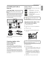
Place the burner caps and heads on the cooktop. 
Make sure that the caps and heads are placed in the 
correct locations. There is one small, one medium, 
one large, one oval(center), and one extra large 
burner head and cap.

Center Burner

(For Model : LSG4513) 

Oval (Center) burner 

head/cap assembly

(For Model : LSG4511)

Medium burner head 

and cap

Small burner 
head and 
cap

Medium 
burner 
head 
and cap

Large burner 

head and cap

Front of range

Extra large burner 

head and cap

Hole

Electrode

Make sure the hole in the burner head is positioned 
over the electrode.

Checking Ignition of the 
Surface Burners

Electric Ignition

Select a surface burner knob and simultaneously 
push in and turn to the 

Lite

 position. You will hear 

a clicking sound indicating proper operation of the 
spark module.
Once the air has been purged from the supply lines 
the burner should ignite within 4 seconds. After the 
burner ignites, rotate the knob out of the 

Lite

 position. 

Try each burner in succession until all burners have 
been checked.

Quality of Flames

The combustion quality of the burner flames needs to 
be confirmed visually.

A  

Yellow flames 

- Call for service.

B  

Yellow tips on outer cones

 - This 

is normal for LP gas.

C  

Soft blue flames

 - This is normal 

for natural gas.

nOTE


With LP gas, some yellow tipping on outer 
cones is normal.

Adjusting the Surface Burner to the 
Low Flame (Simmer) Setting

1

Light all surface burners.

2

Turn the knob on the burner being adjusted to 

Lo

.

3

Remove the knob.

4

Insert a small, flat-blade screwdriver into the 
valve shaft.

nOTE

Hold the valve shaft with one hand while turning 
the screw to adjust with the other.

5

Replace the knob.

6

Test the flame stability.
Test 1: Turn the knob from 

Hi

 to 

Lo

 quickly. If the 

flame goes out, increase the flame size and test 
again.
Test 2: With the burner on a 

Lo

 setting, open 

and close the oven door quickly. If the flame is 
extinguished by the air currents created by the 
door movement, increase the flame height and 
test again.

7

Repeat steps 1-6 for each surface burner.

Summary of Contents for LSG4513BD

Page 1: ...as connector it must not exceed 3 feet in length Preparing for Installation Tools needed Phillips screwdriver Open end or adjustable wrench Pencil and ruler Level Flat blade screwdriver Pipe wrench 2 one for support Materials You May need Gas line shut off valve Pipe joint sealant that resists action of natural and LP gases Flexible metal appliance connector 3 4 or 1 2 NPT x 1 2 I D Never use an o...

Page 2: ...ing the Proper Location Do not locate your range where it may be subject to strong drafts Any openings in the floor or wall behind the range should be sealed Make sure the openings around the base of the range that supply fresh air for combustion and ventilation are not blocked by carpeting or woodwork Your range like many other household units is heavy and can be installed on soft floor coverings...

Page 3: ...djusted to meet specific requirements The range may be placed with 0 clearance flush at the back wall Installation Clearances 30 76 2 cm 30 76 2 cm Minimum 15 38 1 cm 36 91 4 cm 13 33 0 cm Maximum depth for cabinets above coutertops Front edge of the range side panel forward from cabinet 0 To cabinets below cooktop and at the range back 1 4 Dimensions 28 3 4 73 0 cm Height 37 59 64 96 3 cm Depth w...

Page 4: ...idge the opening at the rear wall the rear filler kit that is provided with the slide in range will be needed nOTE If the countertop depth is greater than 25 there will be a gap between the filler kit and the back wall If the countertop depth is less than 24 the control panel will not sit flush with the countertop Installing the rear Filler 1 Using a screwdriver remove the upper four screws that a...

Page 5: ...tion nOTE The gas pressure regulator valve is open when shipped If the range does not work properly after installation make sure the regulator valve is still open 3 Connect a flexible metal appliance connector to the adapter on the range Position the range to permit connection at the shut off valve 4 When all connections have been made be sure all range controls are in the OFF position and the pre...

Page 6: ...h off power when a threshold leakage level is detected These devices must be manually reset by the consumer The National Electrical Code requires the use of GFCI s in kitchen receptacles installed to serve countertop surfaces Performance of the range will not be affected if operated on a GFCI protected circuit but the occasional resetting of the circuit can become an annoyance Ensure proper ground...

Page 7: ...ld ignite within 4 seconds After the burner ignites rotate the knob out of the Lite position Try each burner in succession until all burners have been checked Quality of Flames The combustion quality of the burner flames needs to be confirmed visually A Yellow flames Call for service B Yellow tips on outer cones This is normal for LP gas C Soft blue flames This is normal for natural gas nOTE With ...

Page 8: ...ersions The range comes from the factory with the air shutters adjusted for proper air flow for natural gas If converted to LP follow the instructions provided in the conversion kit to properly adjust the air shutters LP conversion must be performed by a qualified technician Leveling the range Level the range by adjusting the leveling legs Extending the legs slightly may also make it easier to ins...

Reviews: