
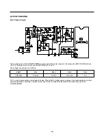
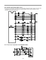
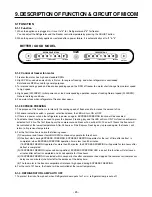
8-2-2 Oscillation Circuit
This circuit generates the base clock for calculating time and the synchro clock for transmitting data from and to the inside
logic elements of the IC1 (MICOM). Be sure to use specific replacement parts, since calculating time by the IC1 may be
changed. If changed, the OSC1 SPEC will not work.
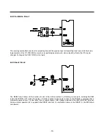
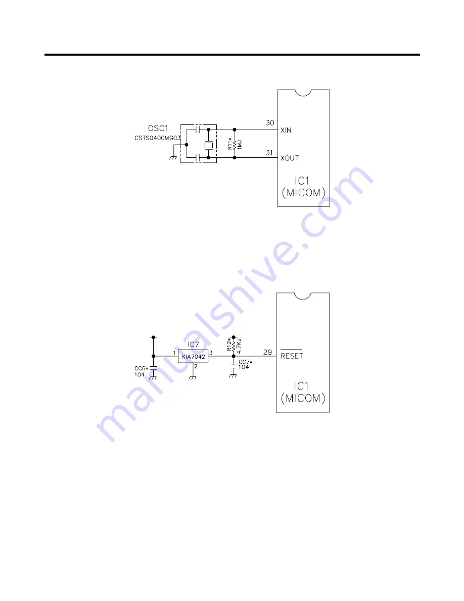
8-2-3 Reset Circuit
The RESET circuit allows all the functions to start at the initial conditions by initializing various parts, including the RAM
inside the MICOM (IC1) when the power is initially supplied or the power supply to the MICOM is restored after a
momentary power failure. For the initial 10ms of power supply, LOW voltage is applied to the MICOM RESET terminal.
During a normal operation, 5V is applied to the RESET terminal. (If a malfunction occurs in the RESET IC, the MICOM will
not operate.)
-
30
-
Summary of Contents for LRBC22522
Page 12: ...GY GRIS GRAY Best Best dispenser 5 CIRCUIT DIAGRAM 12 ...
Page 13: ...GY GRIS GRAY Good Better 13 ...
Page 40: ...8 5 MAIN PWB ASSEMBLY AND PARTS LIST 8 5 1 Main PWB Assembly 40 ...
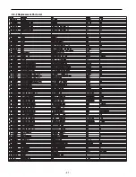
Page 41: ...8 5 2 Replacement Parts List 41 ...
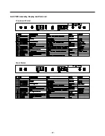
Page 42: ...8 5 3 PWB Assembly Display And Parts List 42 SW106 Dispenser Model Best Model ...
Page 60: ...9 5 MAIN PWB ASSEMBLY AND PARTS LIST 9 5 1 Main PWB Assembly 60 ...
Page 61: ...9 5 2 Replacement Parts List 61 ...
Page 62: ...9 5 3 PWB Assembly Display And Parts List 62 ...
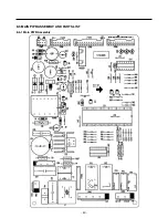
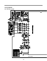
Page 63: ...9 6 PWB DIAGRAM 9 6 1 PWB Main Assembly 63 G5S 1A RY5 ...
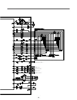
Page 64: ... 64 ...
Page 70: ...June 2009 ...


