
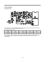
8-1-8 Buzzer Sound
When the button on the front Display is pushed, a Ding~ Dong~ sound is produced.
(Refer to the Buzzer Circuit 8-2-4 No. 3)
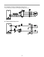
8-1-9 Defrosting (removing frost)
1. Defrosting starts each time the COMPRESSOR running time reaches 7 hours.
2. For initial power on or for restoring power, defrosting starts when the compressor running time reaches 4 hours.
3. Defrosting stops if the sensor temperature reaches 46.4°F(8°C) or more. If the sensor doesn’t reach 46.4°F(8°C) in
2 hours, the defrost mode is malfunctioning. (Refer to the defect diagnosis function, 8-1-13.)
4. Defrosting won’t function if its sensor is defective (wires are cut or short circuited)
8-1-10 Filter Replacement Indication
1. In 6 months after the UNIT (refrigerator) is power on, or after 28,000 seconds of dispenser use, the water filter Indicator
LED (red color) will be ON.
2. When the water filter indicator LED is illuminated, you should change the water filter. After this, you must press the water
filter button for three seconds and you will hear a ding-dong sound.
The LED will be OFF. This operation will indicate that the UNIT is reset to its initial conditions, so this process is restarted.
8-1-11 Power Failure Compensation Function
1. When the UNIT is power off, the Fresh Food and Freezer Temperature notches, the filter elapsed time for replacement,
the temperature mode (°C or °F) and the dispenser lock mode are saved in the EEPROM.
2. When the UNIT is power on, the MICOM will read the specified EEPROM addresses to restore the values indicated in the
previous paragraph.
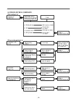
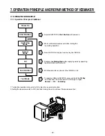
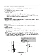
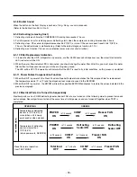
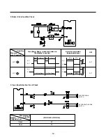
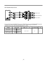
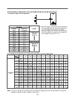
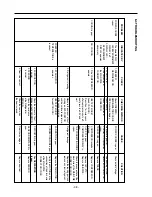
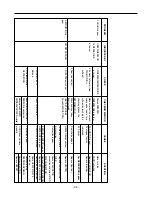
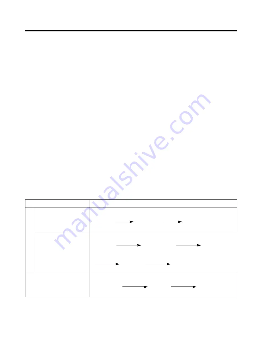
8-1-12 Electrical Parts Are Turned On Sequentially
Electrical parts such as COMP, defrosting heater, freezer FAN, etc. are turned on in the following order to prevent noise and
parts damage. Several parts are started at the same time at initial power on and are turned off together when TEST is
completed.
- 2
6
-
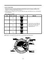
OPERATING
ORDERS
Temperature of Defrosting
Sensor is 113°F(45°C) or
more (when unit is newly
purchased or when moved)
Temperature of defrosting
sensor is lower than
113°F(45°C)
(when power cuts, SERVICE)
Reset to normal operation
from TEST MODE
Initial power on
POWER
ON
in 1/2 second
in 1/2 second
Total load
OFF
COMP
ON
Freezer FAN
ON
in 7 minute
in 1/2 second
COMP
ON
Freezer FAN
ON
POWER
ON
COMP
ON
Freezer FAN
ON
Defrosting
heater ON
Defrosting
heater OFF
in 1/2 second
in 1/2 second
in 1/2 second
in 10 second
Summary of Contents for LRBC22522
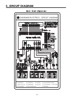
Page 12: ...GY GRIS GRAY Best Best dispenser 5 CIRCUIT DIAGRAM 12 ...
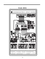
Page 13: ...GY GRIS GRAY Good Better 13 ...
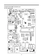
Page 40: ...8 5 MAIN PWB ASSEMBLY AND PARTS LIST 8 5 1 Main PWB Assembly 40 ...
Page 41: ...8 5 2 Replacement Parts List 41 ...
Page 42: ...8 5 3 PWB Assembly Display And Parts List 42 SW106 Dispenser Model Best Model ...
Page 60: ...9 5 MAIN PWB ASSEMBLY AND PARTS LIST 9 5 1 Main PWB Assembly 60 ...
Page 61: ...9 5 2 Replacement Parts List 61 ...
Page 62: ...9 5 3 PWB Assembly Display And Parts List 62 ...
Page 63: ...9 6 PWB DIAGRAM 9 6 1 PWB Main Assembly 63 G5S 1A RY5 ...
Page 64: ... 64 ...
Page 70: ...June 2009 ...


