

- 1
5
-
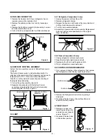
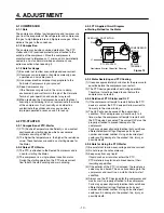
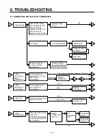
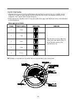
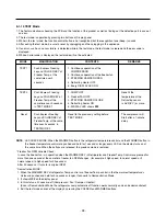
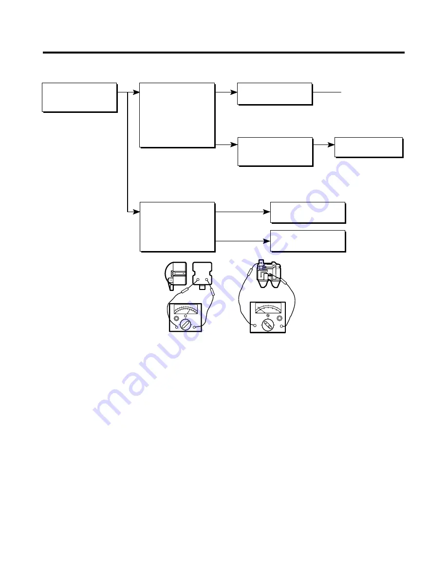
6-2 PTC AND OLP
6
5
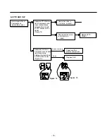
Shows continuity
Open
Normal operation of
Compressor is
impossible or poor.
Separate PTC-Starter
from Compressor and
measure resistance
between No. 5 and 6
of PTC-Starter with a
Tester.
(Figure 14)
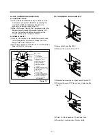
Separate OLP from
Compressor and check
resistance value
between two terminals
of OLP with a Tester.
(Figure 15)
Observation value is
115V/60Hz : 6.8
Ω
±30%
The resistance value
is 0
Ω
(short) or
∞
(open).
Check another
electric component.
Replace OLP.
Replace PTC-
Starter.
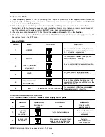
Figure 14
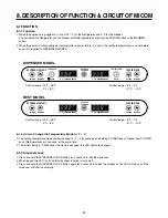
Figure 15
Summary of Contents for LRBC22522
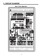
Page 12: ...GY GRIS GRAY Best Best dispenser 5 CIRCUIT DIAGRAM 12 ...
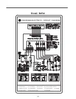
Page 13: ...GY GRIS GRAY Good Better 13 ...
Page 40: ...8 5 MAIN PWB ASSEMBLY AND PARTS LIST 8 5 1 Main PWB Assembly 40 ...
Page 41: ...8 5 2 Replacement Parts List 41 ...
Page 42: ...8 5 3 PWB Assembly Display And Parts List 42 SW106 Dispenser Model Best Model ...
Page 60: ...9 5 MAIN PWB ASSEMBLY AND PARTS LIST 9 5 1 Main PWB Assembly 60 ...
Page 61: ...9 5 2 Replacement Parts List 61 ...
Page 62: ...9 5 3 PWB Assembly Display And Parts List 62 ...
Page 63: ...9 6 PWB DIAGRAM 9 6 1 PWB Main Assembly 63 G5S 1A RY5 ...
Page 64: ... 64 ...
Page 70: ...June 2009 ...


