background image

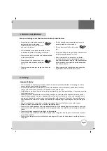
1. Before installation

Page 3

• Solar module installation should be

performed by an authorized
installer for the safety and mainte-
nance of the system.

• All installation instructions should be clearly

understood before attempting installation.

• Do not twist, pull, or scratch the cable attached

to the solar module.

• Do not touch the glass or rear sur-

face of the solar module with bare
hands.

• Do not stand on and put weight on the solar

module.

• Do not drop the solar module and cause an

excessive load on solar module

• Do not disassemble the solar mod-

ule.

• After installation or repair, check whether solar

module operates properly or not.

• Please compare the properties and perfor-

mance between the as-used module or part
and the new module or part if the replacement
of the module or any part should be required
due to breakdown.

• Please contact the local office to confirm the

regulations and to obtain permission.

Please carefully read this manual before installation.

2. Safety

• All installation and safety instructions should be clearly understood before attempting to install,

wire, operate, or maintain the module.

• Contact with electrically active parts of the solar module, such as terminals, could result in burns,

sparks, and lethal shock, whether the module is connected or not.

• Installation or maintenance should only be performed by qualified professionals, in accordance with

local requirements.

• No matter where the modules are installed, whether on roof-mounted construction or any other

type of above-ground structure, appropriate safety practices should be taken and required safety
equipment should be used in order to avoid possible safety hazards. Note that the installation of
some modules on roofs may require the addition of fireproofing, depending on local building/fire
codes.

• Use only equipment, connectors, wiring and support frames suitable for use in solar system.
• Follow all safety precautions of all other used components.
• Do not let anyone approach the solar module who has little knowledge of solar modules or on the

measures to take when solar modules are damaged in order to avoid the risk of injury or electrical
shock.

• Do not artificially concentrate sunlight on the module.
• Do not shade the module surface from sunlight for a long time. Shading can increase the tempera-

ture of the module.

• Do not clean the glass surface with alkaline detergents. Do not let water remain on the glass for a

long time.

- General Safety

Summary of Contents for LG M1C Series

Page 1: ......

Page 2: ...rical Installation 6 Electrical Connections 6 General Wiring 6 Earth Ground Wiring 6 Series Connection 6 Parallel Connection 7 5 Mechanical Installation 7 Module Mounting 7 Site Consideration 7 Mounting Configurations 8 Mechanical characteristics All types 11 6 Product Specification 12 Mono crystalline 12 Poly crystalline 13 7 Ground method 14 ...

Page 3: ...ct with electrically active parts of the solar module such as terminals could result in burns sparks and lethal shock whether the module is connected or not Installation or maintenance should only be performed by qualified professionals in accordance with local requirements No matter where the modules are installed whether on roof mounted construction or any other type of above ground structure ap...

Page 4: ...ate protective equipment Handling Safety Keep the system and modules away from children when installing Keep the module packed in the carton until the time of installation Do not touch the module more than during installation The glass surface and the frames heat up so there is a risk of being burned or shocked when touch ing Do not work under raining snowing or windy conditions Use insulated tool...

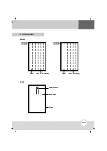
Page 5: ...Page 5 3 Component Front Type A Type B Glass Solar Cell Mono Glass Solar Cell Poly Back Junction Box Backsheet Frame ...

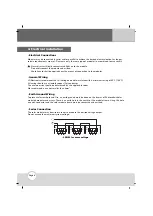
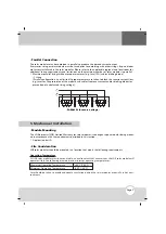
Page 6: ...ith a minimum rating of 90 C 194 F All wiring should use a flexible copper Cu conductor The minimum size should be determined by the applicable codes We recommend a size not smaller than 4mm2 Earth Ground Wiring To prevent electric shock and fire an earth ground must be done on the frames of Photovoltaic solar modules modules and arrays There is an earth hole in the center of the module frame Usin...

Page 7: ...s for the protection of the module and cables from over current and or bloking diodes for prevention of unbalanced string voltage Module Mounting The LG Electronics LGE Limited Warranty for solar modules is contingent upon modules being mount ed in accordance with the requirements described in this section Application class A 5 Mechanical Installation Site Consideration LGE solar modules should be...

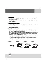
Page 8: ...angle from horizontal to vertical Select the appropriate orien tation to maximize sunlight exposure Specific information on the solar module dimensions and loca tion of mounting and grounding holes is provided below In order to prevent water from entering the junction box which could present a safety hazard module should not be mounted such that the front top glass faces downward Clearance between...

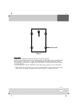
Page 9: ...nsions and mounting hole locations The module may be fastened to a support using the bolt holes in the bottom of the frame at location A refer to Figure 1 The module should be fastened with M6 bolts plain washers spring washers and nuts for support A gap between the solar module frame and the installation object is necessary for cooling air circu lation Do not seal this gap The recommended standof...

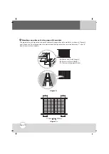
Page 10: ...solar modules as shown in Figures 2 and 3 Note that the clip positions are maintained the clip centerlines must be between 7 and 16 from the end of the module A B C Figure 2 A 30mm min Catch Length B 5mm min Catch Width C 10mm min Support Width B Mounting using clips on the long edge of the module ...

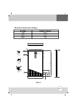
Page 11: ...Mechanical characteristics All types Mounting slots 8 places Junction Box Detail A Scale 1 5 Detail B Scale 1 5 Detail C Scale 1 5 Grounding holes 4 places Drain holes 4 places Drain holes 8 places 993 954 993 2 4 3 11x6 5 2 5 5 6 5 11 6 12 R3 R3 25 12x5 1649 23 4 370 205 105 42 Figure 4 ...

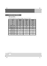
Page 12: ...49A 235W 3 0 1 000V 15A 60each 3 3 15A each 0 47 K 0 05 K 0 34 K 36 9V 29 7V 8 10A 8 58A 240W 3 0 1 000V 15A 60each 3 3 15A each 0 47 K 0 05 K 0 34 K 6 Product Specification Voc Vmp Imp Isc Pmax Output Tolerance Maximum System Voltage Maximum Series Fuse Total Number of Cells Total Number of Strings Diodes Rating Temperature coefficient of power TkPmax Temperature coefficient of current TkImp Temp...

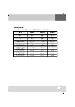
Page 13: ... 0V 7 76A 8 30A 225W 3 0 1 000V 15A 60each 3 3 15A each 0 47 K 0 05 K 0 34 K 36 4V 29 1V 7 91A 8 39A 230W 3 0 1 000V 15A 60each 3 3 15A each 0 47 K 0 05 K 0 34 K Voc Vmp Imp Isc Pmax Output Tolerance Maximum System Voltage Maximum Series Fuse Total Number of Cells Total Number of Strings Diodes Rating Temperature coefficient of power TkPmax Temperature coefficient of current TkImp Temperature coef...

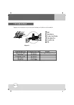
Page 14: ...imension material Remark Hexagon nut bolt Plain washer Toothed lock washer Screw washer Ground wire M4 stainless M4 stainless M4 stainless M4 stainless 12 AWG copper The length of the bolt 15 mm F B E D A B C B Bolt A Plain Washer B Toothed Lock Washer C Grounding Wire D Screw Washer E Nut F Figure 5 7 Ground method ...

Page 15: ...Page 15 Memo ...

Page 16: ......

Reviews: