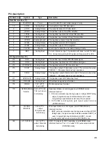
Pin description
45
Pin Numbers
Symbol Type
Description
Data PLL Interface (11)
11
PLLVDD33
Power
Power for data PLL and related analog circuitry.
10
JITFN
Analog Input
The input terminal of RF jitter meter.
9
JITFO
Analog Output
The output terminal of RF jitter meter.
8
LPFOP
Analog Output
The positive output of loop filter amplifier.
7
LPFIN
Analog Input
The negative input terminal of loop filter amplifier.
6
LPFIP
Analog Input
The positive input terminal of loop filter amplifier.
5
LPFON
Analaog Ouptut
The negative ouotput of loop filter amplifier.
4
LPION
Analog Output
The negative output of VCO integrator.
3
LPIOP
Analog Output
The positive output of VCO integrator.
2
PLLVSS
Ground
Ground pin for data PLL and related analog circuitry.
1
IREF
Analog Input
Current reference input. It generate reference current for data
PLL. Connect an external 8.2K resistor to this pin and PLLVSS.
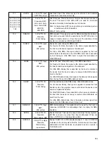
RF Signal Interface (16)
216
RFIP
Analog Input
The positive input terminal RF differential signal.
215
RFIN
Analog Input
The negative input terminal of RF differential signal.
214
RFDTSLVN
Analog Output
The negative output of RF data slicer level
213
SCOP
Analog Output
The positive output of data slicer current. This pin is active when
TRONS= 1. Otherwise this pin is high inpedence.
212
SCON
Analog Output
The negative output of data slicer current. This pin is active when
TRONS= 1. Otherwise this pin is high inpedence.
211
RFDTSLVP
Analog Output
The positive ouput of RF data slicer level.
203
RFSUBI
Analog Input
RF subtraction signal input terminal.
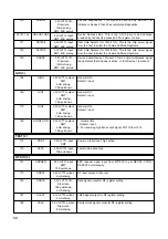
174
WBLSI
3.3V LVTTL
Wobble signal input terminal
Input, SMT
179
RLDON(UDGA
3.3V LVTTL I/O,
Read laser diode on control signal.(non-DVDRAM mode)
Alternate function :
1. ICE mode selection input during power-on stage (PRST falling
edge). A logical low input indicates internal µP is used.
A logical high input indicates external µP is connected.
2. DVD-RAM recording data gate signal output terminal
(DVDRAM mode).
177
WLDON
3.3V LVTTL ,
Write laser diode on control signal. (non-DVDRAM mode)
Alternate function:
1. HRST_extension selection input during power-on stage (PRST
falling edge). A logical low input indicates extended HRST_ is
used. A logical high input indicates raw HRST_ is used.
2. Header detect signal output terminal (DVDRAM mode)
182
H11T(VFO13)
3.3V LVTTL
EFM 11T indicator for ROPC sampling. (non-DVDRAM mode)
Alternate function: The 1
st
, 3
rd
header VFO pulse output terminal
(DVDRAM mode)
TE)/ICE
(IDGATE)
75K pull-down,
4mA driving.
output,
75K pull-down,
4mA driving
output, Slew rate
8mA driving

