4-3
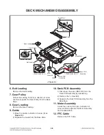
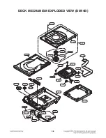
DECK MECHANISM DISASSEMBLY
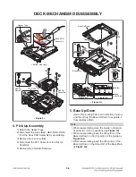
3) Grasp the both sides of the Tray Disc and lift
it up as
Figure D
, and then pull the Tray Disc
until it is separated from the MD Sub Assembly
completely.
Note
• When reassembling place the Guide as
Figure E
.
MD Sub
Assembly
< Figure D >
3
1
1
2
2
Tray Disc
Tray Disc
< Figure E >
Guide
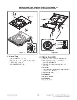
3. Tray Disc
1) Insert and push a flat-head screwdriver in the
Emergency eject hole (H1) at the right side, so
that the Tray Disc is ejected about 15 ~ 20 mm.
2) Pull the Tray Disc until it is locked.
< Bottom side view >
Tray Disc
Tray Disc
< Figure C >
2
1
(H1)
Emergency eject hole
Summary of Contents for CJ87
Page 17: ...1 16 ...
Page 19: ...2 2 ...
Page 21: ...2 6 2 5 ...
Page 23: ...2 8 A60 3 SPEAKER SECTION FRONT SPEAKER ...
Page 69: ...3 40 ...
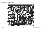
Page 73: ...3 47 3 48 PRINTED CIRCUIT BOARD DIAGRAMS 1 SMPS P C BOARD DIAGRAM TOP VIEW ...
Page 75: ...3 51 3 52 2 MAIN P C BOARD DIAGRAM TOP VIEW ...
Page 76: ...3 53 3 54 MAIN P C BOARD DIAGRAM BOTTOM VIEW ...
Page 77: ...3 55 3 56 3 FRONT P C BOARD DIAGRAM TOP VIEW ...
Page 78: ...3 57 3 58 FRONT P C BOARD DIAGRAM BOTTOM VIEW ...
Page 79: ...3 59 3 60 4 JACK P C BOARD DIAGRAM TOP VIEW BOTTOM VIEW ...

