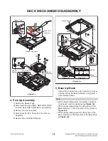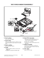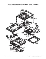
4-2
DECK MECHANISM DISASSEMBLY
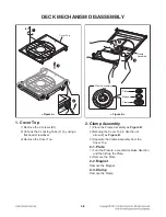
1. Cover Top
1) Remove the 2 screws (S1).
2) Unhook the 4 Locking Tabs (L1) by using a
flat-head screwdriver.
3) Remove the Cover Top.
2. Clamp Assembly
1) Place the Clamp Assembly as
Figure B
.
2) Bending the Cover Top in direction of
arrow (2) as
Figure B
.
3) Separate the Clamp Assembly from the
Cover Top.
2-1. Plate
1) Turn the Plate to a counterclockwise direction
and then lift up the Plate.
2) Remove the Plate.
2-2. Magnet
Remove the Magnet.
2-3. Clamp
Remove the Clamp.
1
3
(S1)
(L1)
Cover Top
< Figure A >
2
1
2
< Figure B >
Clamp
Assembly
Clamp Assembly
Plate
Magnet
Clamp
Summary of Contents for CJ87
Page 17: ...1 16 ...
Page 19: ...2 2 ...
Page 21: ...2 6 2 5 ...
Page 23: ...2 8 A60 3 SPEAKER SECTION FRONT SPEAKER ...
Page 69: ...3 40 ...
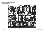
Page 73: ...3 47 3 48 PRINTED CIRCUIT BOARD DIAGRAMS 1 SMPS P C BOARD DIAGRAM TOP VIEW ...
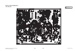
Page 75: ...3 51 3 52 2 MAIN P C BOARD DIAGRAM TOP VIEW ...
Page 76: ...3 53 3 54 MAIN P C BOARD DIAGRAM BOTTOM VIEW ...
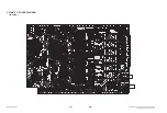
Page 77: ...3 55 3 56 3 FRONT P C BOARD DIAGRAM TOP VIEW ...
Page 78: ...3 57 3 58 FRONT P C BOARD DIAGRAM BOTTOM VIEW ...
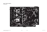
Page 79: ...3 59 3 60 4 JACK P C BOARD DIAGRAM TOP VIEW BOTTOM VIEW ...

