background image

20

ENGLISH

A B

E

B

I

A

B

D

C

1m

1m

D

F

G

B

G

D

B

H

I

J

A


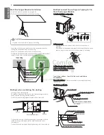
Sleeve


Heat insulating material


Lagging


Caulking material


Band


Waterproofing layer


Sleeve with edge


Lagging material


Mortar or other incombustible caulking


Incombustible heat insulation material

When filling a gap with mortar, cover the penetration part with steel plate so

that the insulation material will not be caved in. For this part, use

incombustible materials for both insulation and covering. (Vinyl covering

should not be used.)

Inner wall (concealed)

Outer wall

Outer wall (exposed)

Floor (fireproofing) 

Penetrating portion on fire
limit and boundary wall

Roof pipe shaft 

- Install the Outside Unit communication cable away from the power

source wiring so that it is not affected by electric noise from the power

source. (Do not run it through the same conduit.)

- Be sure to provide designated grounding work to Outside Unit.

- Give some allowance to wiring for electrical part box of Indoor and

Outside Units, because the box is sometimes removed at the time of

service work.

- Communication between the compressor module and the condenser

module must be connected at a fixed site on the terminal block. 

- Never connect the main power source to terminal block of

communication cable. If connected, electrical parts will be burnt out. 

- Use 2-core shield cable for communication cable.(     mark in the

figure below) If communication cable of different systems are wired

with the same multiplecore cable, the resultant poor transmitting and

receiving will cause erroneous operations. (      mark in the figure

below)

- Only the communication cable specified should be connected to the

terminal block for Outside Unit communication.

CAUTION

Be sure to correct the outside unit to earth. Do not connect ground

wire to any gas pipe, liquid pipe, lightening rod or telephone earth

line. If earth is incomplete, it may cause an electric shock.

!

WARNING

Be sure to have authorized electrical engineers do the electric

work using special circuits in accordance with regulations and this

installation manual.

If power supply circuit has a lack of capacity or electric work

deficiency, it may cause an electric shock or fire.

!

2-Core Shield Cable

Multi-Core Cable

Remote

control

Remote

control

Remote

control

Remote

control

Indoor

Unit

Indoor

Unit

Indoor

Unit

Indoor

Unit

Compressor Module Heat Exchanger

Module

Compressor Module Heat Exchanger

Module

Remote

control

Remote

control

Indoor

Unit

Indoor

Unit

Remote

control

Remote

control

Indoor

Unit

Indoor

Unit

Compressor Module Heat Exchanger

Module

Compressor Module Heat Exchanger

Module

Precautions when laying power wiring

Use round pressure terminals for connections to the power terminal

block.

Round pressure terminal

Power cable

- For wiring, use the designated power cable and connect firmly, then

secure to prevent outside pressure being exerted on the terminal

block.

- Use an appropriate screwdriver for tightening the terinal screws. A

screwdriver with a small head will strip the head and make proper

tighterning impossible.

- Over-tightening the terminal screws may break them.

CAUTION

• Use the 2-core shield cables for communication cables. Never use

them together with power cables.

• The conductive shielding layer of cable should be grounded to the

metal part of both units.

• Never use multi-core cable

• As this unit is equipped with an inverter, to install a phase leading

capacitor not only will deteriorate power factor improvement effect,

but also may cause capacitor abnormal heating. Therefore, never

install a phase leading capacitor.

• Make sure that the power unbalance ratio is not greater than 2%. 

If it is greater the units lifespan will be reduced.  

!

When none are available, follow the instructions below.

- Do not connect wiring of different thicknesses to the power terminal

block. (Slack in the power wiring may cause abnormal heat.)

- When connecting cable which is the same thickness, do as shown in

the figure below.

ELECTRICAL WIRING

Caution

- Follow ordinance of your governmental organization for technical

standard related to electrical equipment, wiring regulations and

guidance of each electric power company.

Penetrations

www.lgcomfortcooling.co.uk

Summary of Contents for ARUN050GME0

Page 1: ...REA For more information Refer to the CD or LG Web site www lg com AIR CONDITIONER www lg com Please read this installation manual completely before installing the product Installation work must be performed in accordance with the national wiring standards by authorized personnel only Please retain this installation manual for future reference after reading it thoroughly Copyright 2018 LG Electron...

Page 2: ...c shock Always intstall a dedicated circuit and breaker Improper wiring or installation may cause fire or electric shock For re installation of the installed product always contact a dealer or an Authorized Service Center There is risk of fire electric shock explosion or injury Do not install remove or re install the unit by yourself customer There is risk of fire electric shock explosion or injur...

Page 3: ...d harzards due to lack of oxygen in the room could result Means for disconnection must be incorporated in the fixed wiring in accordance with the wiring rules If the supply cord is damaged it must be replaced by the manufacturer its service agent or similarly qualified persons in order to avoid a hazrd This equipment shall be provided with a supply conductor complying with the national regulation ...

Page 4: ...roduct malfunction or inefficient operation Operation Do not use the air conditioner in special environments Oil steam sulfuric smoke etc can significantly reduce the performance of the air conditioner or damage its parts Do not block the inlet or outlet It may cause failure of appliance or accident Make the connections securely so that the outside force of the cable may not be applied to the term...

Page 5: ...LECT THE BEST LOCATION COMPRESSOR MODULE 7 INSTALLATION SPACE COMPRESSOR MODULE 7 SELECT THE BEST LOCATION HEAT EXCHANGER MODULE 7 INSTALLATION SPACE HEAT EXCHANGER MODULE 8 CARRYING METHOD 8 INSTALLATION COMPRESSOR MODULE 8 The location of the Anchor bolts 8 Foundation for Installation 9 INSTALLATION HEAT EXCHANGER MODULE 10 Heat Exchanger Module Installation 10 Method when insatalling the ductin...

Page 6: ...national regulations for the designed pressure 3 8MPa Since R410A is a mixed refrigerant the required additional refrigerant must be charged in its liquid state If the refrigerant is charged in its gaseous state its composition changes and the system will not work properly Compressor Module Power Supply 380 415 V 3N 50 Hz CAUTION Ratio of the connectable Indoor Units to the Outdoor Within 50 130 R...

Page 7: ...indoors Ambient design temprature of compressor module and Heat exchange module is 5 35 C 26 C WB Select space for installing compressor module which will meet the following conditions No direct thermal radiation from other heat sources Do not installation where sensitive place the noise No exposition to strong wind With strength which bears weight of unit Note that drain flows out of unit when he...

Page 8: ...Concrete support WARNING Install where it can sufficiently support the weight of the compressor module If the support strength is not enough the compressor module may drop and hurt people Install where the compressor module may not fall in strong wind or earthquake If there is a fault in the supporting conditions the outside unit may fall and hurt people Please take extra cautions on the supportin...

Page 9: ... place where the module can withstand its vibration A place where service can be easily performed Dimension Chassis A B C D E F G H I J K L B8 1680 1565 1160 330 460 580 700 1400 1635 390 445 15 Unit mm B8 Chassis M10 Nut M10 washer X 4 X 4 M10 Nut M10 washer X 4 X 8 NOTE Throughly study the following installation locations 1 In such places as restaurants and kitchens considerable amount of oil st...

Page 10: ...Thermal insulator for refrigerant pipe Local supply Hose crip for thermal insulator Local supply CAUTION Tighten the nut and bolt to prevent unit falling Heat Exchanger Module Installation Select and mark the position for fixing bolts Drill the hole for set anchor on the face of ceiling Insert the set anchor and washer onto the suspension bolts for locking the suspension bolts on the ceiling Mount...

Page 11: ...dule Preparation of Piping Main cause of gas leakage is defect in flaring work Carry out correct flaring work in the following procedure Cut the pipes and the cable Use the accessory piping kit or the pipes purchased locally Measure the distance between the indoor and the outside unit Cut the pipes a little longer than measured distance Cut the cable 1 5m longer than the pipe length Burrs removal ...

Page 12: ...d warm Clogging of EEV Capillary Gas shortages Degradation of refrigerant oil Poor insulation of the compressor Do not cold and warm Counter measur e No moisture in the pipe Until the connection is completed the plumbing pipe entrance should be strictly controlled Stop plumbing at rainy day Pipe entrance should be taken side or bottom When removal burr after cutting pipe pipe entrance should be ta...

Page 13: ...n cap Liquid Pipe to Heat Exchanger Module Gas Pipe to Heat Exchanger Module Charging Port Gas Pipe to Indoor Unit Liquid Pipe to Indoor Unit Method of drawing out pipes on the rear side Proceed with the pipe work as shown in the below figure for rear side pie drawing out Pipe Drawing Out Method of out pipes on the top side Cover the uninstalled area with a cover Close the cover with the screw Clo...

Page 14: ...ction Branching section Indoor unit Gas pipe Main pipe Liquid pipe Branching pipe Branching pipe Indoor unit Compressor Unit Condenser Unit Selection of Refrigerant Piping Y branch method ⓐ Compressor Module ⓑ Heat Exchanger Module ⓒ 1st branch Y branch ⓔ Indoor Units d ℓ 40 m h 15m H2 30m L2 70 m Indoor Unit A B C D E e e a c e e e e b e H1 10m L1 30 m Combination of Y branch header ⓐ Compressor ...

Page 15: ...r header branching It is recommended that difference in length of the pipes connected to the indoor units a f is minimized Performance difference between indoor units may occur Indoor units should be installed at lower position than the header Connection method Mark Y branch only Combination of Y branch header Header only Longest pipe length Heat Exchanger Module Compressor Module L1 A 30 m A 30 m...

Page 16: ...ow pressure side Handle Ⓒ High pressure side Handle WARNING Pipe to be vacuumed gas pipe liquid pipe If the refrigerant amount is not exact it may not operate properly If additionally bottled refrigerant amount is over 10 condenser burst or insufficient indoor unit performance may be caused Volume of the room at which Indoor Unit of the least capacity is installed Total amount of refrigerant in th...

Page 17: ... Horizontal plane Within 10 A Ⓐ To Branch Piping or Indoor Unit Ⓑ To Outdoor Unit Ensure that the branch pipes are attached horizontally or vertically see the diagram below Branch pipe Fitting Joints between branch and pipe should be sealed with the tape included in each kit Any cap pipe should be insulated using the insulator provided with each kit and then taped as described above Insulator Insu...

Page 18: ...ake Vacuum from liquid pipe gas pipe and high low pressure common pipe with the service valve closed Never perform air purging using refrigerant Vacuum drying Use a vacuum pump that can evacuate to 100 7kPa 5 Torr 755mmHg Evacuate the system from the liquid and gas pipes with a vacuum pump for over 2 hrs and bring the system to 100 7kPa After maintaining system under that condition for over 1 hr c...

Page 19: ...ation work is insufficient there is a possibility of condensation drip etc Pay special attention to insulation work to ceiling plenum Ⓐ Heat insulation material Ⓑ Pipe Ⓒ Outer covering Wind the connection part and cutting part of heat insulation material with a finishing tape Heat insulation material Adhesive Heat resistant polyethylene foam Adhesive tape Outer covering Indoor Vinyl tape Floor exp...

Page 20: ...ial circuits in accordance with regulations and this installation manual If power supply circuit has a lack of capacity or electric work deficiency it may cause an electric shock or fire 2 Core Shield Cable Multi Core Cable Remote control Remote control Remote control Remote control Indoor Unit Indoor Unit Indoor Unit Indoor Unit Compressor Module Heat Exchanger Module Compressor Module Heat Excha...

Page 21: ... 5mm2 Maximum allowable temperature 60 C Maximum allowable cable length under 300m Remote control cable Types 3 core cable Central control cable Separation of communication and power cables If communication and power cables are run alongside each other then there is a strong likelihood of operational faults developing due to interference in the signal wiring caused by electrostatic and electromagn...

Page 22: ...3 4 3 4 3 4 Communication Cable Wiring Compressor Module SODU B SODU A IDU B IDU A CEN B CEN A DRY1 DRY2 GND 12V 3 4 Indoor Unit Indoor Unit Indoor Unit Hex Module Heat Pump Between Indoor unit and Outside unit The GND terminal at the main PCB is a terminal for dry contact it is not the point to make ground connection Example Connection of transmission wire BUS type STAR type Connection of communi...

Page 23: ...on for 5 sec SW01C 7 segment LED 88 Don t press RED Button SW01C Waiting about 2 7 minutes 7 segment LED OK YES NO Check the connections of communication cable 88 Setting the function Select the mode function option value using Button and confirm that using the button after dip switch No 5 is turned on DIP SW01 7 Segment SW01C confirm SW02C ඔ backward SW03C ඖ forward SW04C cancel SW01D reset Autom...

Page 24: ...e OFF except when installing the only 4 series indoor units named ARNU 4 FAN Maximum RPM of each step Mode Function Option Value Action Remarks Content Display1 Content Display2 Content Display3 Content Display4 Implement Display5 Installation Cool Heat Selector oFF op1 op2 Selected the option Change the set value Blank Save in EEPROM Static pressure compensation oFF op1 op3 Selected the option Ch...

Page 25: ...e button Target pressure is set Select the Option using Button HEAT COOL Push the button CAUTION Ask an authorized technician to setting a function If do not use a function set an off mode Change a power consumption or capacity Setting Mode Purpose Condensing temperature variation Evaporating temperature variation Heat Cool op1 Increase capacity Increase capacity 2 C 3 C op2 Decrease power consump...

Page 26: ... Current Outdoor Unit Inverter Compressor Fault OR Drive Fault 3 2 1 Outdoor Unit Inverter Compressor1 High Discharge Temperature Outdoor Unit Inverter Compressor1 High Discharge Temperature 3 4 1 High Pressure of Outdoor Unit High Pressure of Outdoor Unit 3 5 1 Low Pressure of Outdoor Unit Low Pressure of Outdoor Unit 3 6 1 Outdoor Unit Low Compression Ratio Limited Outdoor Unit Low Compression R...

Page 27: ...ve Unit signal at main PCB of Master Outdoor Unit 1 0 5 Master Outdoor Unit Fan PCB Communication Error Failing to receive fan signal at main PCB of Master unit 1 0 6 Master Outdoor Unit FAN IPM Fault Error Instant Over Current at Master Outdoor Unit Fan IPM 1 0 7 Master Outdoor Unit Fan DC Link Low Voltage Error Master Outdoor Unit Fan DC Link Input Voltage is under 380V 1 1 3 Master Outdoor Unit...

Page 28: ...cility kg Capacity of smallest room whereindoor unit is installed m3 In case the result of calculation exceeds the limiting concentration perform the same calculations by shifting to the second smallest and the third smallest rooms until at last the result is below the limiting concentration Refrigerant concentration kg m3 R410A In case the concentration exceeds the limit When the concentration ex...

Page 29: ...f exposure of the workforce include the characteristics of the work room and the other sources of noise i e the number of equipment and other adjacent processes and the length of time for which an operator exposed to the noise Also the permissible exposure level can vary from country to country This information however will enable the user of the equipment to make a better evaluation of the hazard...

Page 30: ...30 ENGLISH www lgcomfortcooling co uk ...

Page 31: ...www lgcomfortcooling co uk ...

Reviews: