


I-6
Service Manual
7541-03x
Logical protocol
2-58
843.00 Carriage Home
2-59
844.00 Lamp failure (Front side)
2-59
849.01 Device had modem installed, but config ID
indicates it should not
2-59
849.10 Device had HD installed, but config ID indicates
it should not
2-59
941 SDRAM R/W error
2-65
941.03 - CPU error
2-65
941.04 - MCD controller error
2-66
941.05 - EEPROM error
2-66
959.xx - Service invalid firmware error
2-68
ON / OFF switch automatically switching to the Off
position
2-48
SIZE SENSING
3-12
Speaker removal
4-25
specifications
1-6
acoustics
1-5
clearances
1-4
dimensions
1-4
electrical
1-4
environment
1-5
memory
1-6
performance
1-6
Power specifications
1-4
processor
1-6
Static discharge brush removal
4-185
Stepper motor removal
4-205
Sub drive unit removal
4-84
Sub frame unit removal
4-104
T
Temperature and humidity sensor removal
4-101
Theory of operation
Color theory
3-47
Printer engine
3-29
Scanner
3-44
Theta sensor removal
4-56
Toner sensor removal
4-97
tools required
1-15
Torque limiter removal
4-185
Transfer belt – CRU removal
4-40
Transfer belt motor removal
4-100
transfer belt position sensor removal
4-41
Transfer belt up down check
2-96
Transfer Roll - CRU removal
4-72
Transport sensor removal
4-203
Tray lift motor removal
4-206
U
Unable to print from USB thumb drive service check
2-97
Upper and lower registration springs removal
4-185
USB HS Test Mode
3-23
USB port service check
2-89
USB Scan to Local
3-11
User attendance messages (0–99)
2-72
W
waste toner bottle missing service check
2-97
Words on fax are stretched
2-86
Wrong paper size service check - tray1
2-98
Wrong paper size service check - tray2
2-98
Summary of Contents for X295
Page 14: ...xiv Service Manual 7541 03x Go Back Previous Next ...
Page 138: ...2 100 Service Manual 7541 03x Go Back Previous Next ...
Page 188: ...3 50 Service Manual 7541 03x Go Back Previous Next ...
Page 306: ...4 118 Service Manual 7541 03x Go Back Previous Next 5 Remove the screw C 6 Remove the screw D ...
Page 307: ...Repair information 4 119 7541 03x Go Back Previous Next 7 Remove the screw E ...
Page 400: ...4 212 Service Manual 7541 03x Go Back Previous Next ...
Page 404: ...5 4 Service Manual 7541 03x Go Back Previous Next Rip Board connectors ...
Page 410: ...5 10 Service Manual 7541 03x Go Back Previous Next Printhead controller connectors ...
Page 419: ...Locations 5 19 7541 03x Go Back Previous Next Engine board connectors ...
Page 438: ...5 38 Service Manual 7541 03x Go Back Previous Next ...
Page 440: ...6 2 Service Manual 7541 03x Go Back Previous Next ...
Page 442: ...7 2 Service Manual 7541 03x Go Back Previous Next Assembly 1 Covers ...
Page 444: ...7 4 Service Manual 7541 03x Go Back Previous Next Assembly 2 Flatbed and ADF ...
Page 446: ...7 6 Service Manual 7541 03x Go Back Previous Next Assembly 3 Flatbed ...
Page 448: ...7 8 Service Manual 7541 03x Go Back Previous Next Assembly 4 ADF 1 ...
Page 450: ...7 10 Service Manual 7541 03x Go Back Previous Next Assembly 5 ADF 2 ...
Page 452: ...7 12 Service Manual 7541 03x Go Back Previous Next Assembly 6 Duplex components 1 ...
Page 454: ...7 14 Service Manual 7541 03x Go Back Previous Next Assembly 7 Duplex components 2 ...
Page 456: ...7 16 Service Manual 7541 03x Go Back Previous Next Assembly 8 Paper exit ...
Page 458: ...7 18 Service Manual 7541 03x Go Back Previous Next Assembly 9 Base 1 ...
Page 460: ...7 20 Service Manual 7541 03x Go Back Previous Next Assembly 10 Base 2 ...
Page 462: ...7 22 Service Manual 7541 03x Go Back Previous Next Assembly 11 Base 3 ...
Page 466: ...7 26 Service Manual 7541 03x Go Back Previous Next Assembly 13 Electrical 1 ...
Page 468: ...7 28 Service Manual 7541 03x Go Back Previous Next Assembly 14 Electrical 2 ...
Page 470: ...7 30 Service Manual 7541 03x Go Back Previous Next Assembly 15 Upper assembly ...
Page 474: ...7 34 Service Manual 7541 03x Go Back Previous Next Assembly 17 Paper trays ...
Page 476: ...7 36 Service Manual 7541 03x Go Back Previous Next Assembly 18 Fuser ...
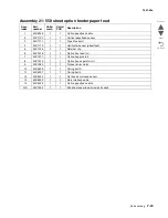
Page 478: ...7 38 Service Manual 7541 03x Go Back Previous Next Assembly 19 550 sheet option feeder covers ...
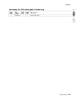
Page 480: ...7 40 Service Manual 7541 03x Go Back Previous Next Assembly 20 550 sheet option feeder base ...
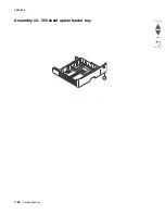
Page 484: ...7 44 Service Manual 7541 03x Go Back Previous Next Assembly 22 550 sheet option feeder tray ...


