


Index
I-3
1234
xxx
recommended types
1-9
unacceptable
1-10
memory
1-6
menus
3-6
messages, attendance
2-69
Min Copy Memory
3-13
Model Name
3-25
models
1-1
Modem removal
4-94
MPF clutch removal
4-174
MPF pad removal
4-192
N
network card option service check
2-94
networking service check
2-87
No dial tone
2-86
NumPad Job Assist
3-13
O
Op panel paper exit guide removal
4-32
operator panel
description
3-1
indicator light
3-1
,
3-2
,
3-3
,
3-4
operator panel service check
2-90
option card service check
2-89
,
2-93
Option controller board removal
4-205
Option door inter lock switch removal
4-207
options and features
description
1-3
Output bin full sensor actuator removal
4-26
P
Panel Menus
3-12
Panel Test
3-21
paper
1-6
recommended types
1-9
unacceptable
1-10
paper and media
paper checks
2-2
Paper empty sensor removal
4-204
paper exit guide removal
4-33
paper exit sensor removal
4-37
Paper feed clutch removal
4-208
Paper feed motor removal
4-110
Paper feed roll removal
4-201
paper feed unit removal
4-68
Paper full sensor removal
4-204
Paper has entered the duplex unit (Paper jam 230, 231-9)
2-26
Paper has entered the fuser and exited the printer (Paper
jam 203)
2-25
Paper has exited the registration roller and entered the
fuser (Paper jam 201)
2-25
Paper has stopped at the registration roller or has not
reached the fuser (Paper jams 200, 250, 24x)
2-25
Paper in ADF size service check
2-99
Paper is being picked up and carried to the registration
roller (Paper jams 200, 250, 24x).
2-24
paper jam
200
2-18
201
2-18
203
2-19
230
2-20
231-39
2-21
24x
2-22
250
2-23
Clearing and troubleshooting paper jams
2-18
Paper level sensor removal
4-203
Paper path service checks
2-24
Paper Prompts
3-15
paper size sensor removal
4-42
Paper size switch removal
4-105
Paper size switches removal
4-202
paper skew service check
2-92
Paper specifications
1-6
paper specifications
media types
1-7
media weights
1-8
paper sizes supported
1-6
Paperfeed roll removal
4-187
Paperfeed unit clutch removal
4-183
Papertray lift motor removal
4-94
Par 1 Strobe Adj
3-26
parts catalog
covers
7-2
performance
1-6
photoconductor lock removal
4-43
Pick roll removal
4-187
,
4-201
POR sequence
2-3
Power supply (Dead machine) service check
2-95
Power supply fan removal
4-55
power-on sequence (POR)
2-3
PPDS Emulation
3-12
print quality
print quality test pages
3-21
Print Quality Pages
3-11
PRINT TESTS
Print Quality Pgs
3-21
Quick Test Page
3-20
Printhead controller board / engine board replacement
4-2
printhead controller board removal
4-37
Printhead service check
2-96
processor
1-6
Q
Quick Disk Test
3-23
Quick Test Page
3-20
R
Rear EMI shield – Not a FRU removal
4-106
Rear fan removal
4-102
Registration roll removal
4-189
Registration sensor (MPF tray) removal
4-184
Registration sensor actuator removal
4-184
removal
bin full sensor removal
4-36
cassette stopper removal
4-44
density sensor removal
4-57
Door interlock switch removal
4-89
Duplex removal
4-63
Summary of Contents for X295
Page 14: ...xiv Service Manual 7541 03x Go Back Previous Next ...
Page 138: ...2 100 Service Manual 7541 03x Go Back Previous Next ...
Page 188: ...3 50 Service Manual 7541 03x Go Back Previous Next ...
Page 306: ...4 118 Service Manual 7541 03x Go Back Previous Next 5 Remove the screw C 6 Remove the screw D ...
Page 307: ...Repair information 4 119 7541 03x Go Back Previous Next 7 Remove the screw E ...
Page 400: ...4 212 Service Manual 7541 03x Go Back Previous Next ...
Page 404: ...5 4 Service Manual 7541 03x Go Back Previous Next Rip Board connectors ...
Page 410: ...5 10 Service Manual 7541 03x Go Back Previous Next Printhead controller connectors ...
Page 419: ...Locations 5 19 7541 03x Go Back Previous Next Engine board connectors ...
Page 438: ...5 38 Service Manual 7541 03x Go Back Previous Next ...
Page 440: ...6 2 Service Manual 7541 03x Go Back Previous Next ...
Page 442: ...7 2 Service Manual 7541 03x Go Back Previous Next Assembly 1 Covers ...
Page 444: ...7 4 Service Manual 7541 03x Go Back Previous Next Assembly 2 Flatbed and ADF ...
Page 446: ...7 6 Service Manual 7541 03x Go Back Previous Next Assembly 3 Flatbed ...
Page 448: ...7 8 Service Manual 7541 03x Go Back Previous Next Assembly 4 ADF 1 ...
Page 450: ...7 10 Service Manual 7541 03x Go Back Previous Next Assembly 5 ADF 2 ...
Page 452: ...7 12 Service Manual 7541 03x Go Back Previous Next Assembly 6 Duplex components 1 ...
Page 454: ...7 14 Service Manual 7541 03x Go Back Previous Next Assembly 7 Duplex components 2 ...
Page 456: ...7 16 Service Manual 7541 03x Go Back Previous Next Assembly 8 Paper exit ...
Page 458: ...7 18 Service Manual 7541 03x Go Back Previous Next Assembly 9 Base 1 ...
Page 460: ...7 20 Service Manual 7541 03x Go Back Previous Next Assembly 10 Base 2 ...
Page 462: ...7 22 Service Manual 7541 03x Go Back Previous Next Assembly 11 Base 3 ...
Page 466: ...7 26 Service Manual 7541 03x Go Back Previous Next Assembly 13 Electrical 1 ...
Page 468: ...7 28 Service Manual 7541 03x Go Back Previous Next Assembly 14 Electrical 2 ...
Page 470: ...7 30 Service Manual 7541 03x Go Back Previous Next Assembly 15 Upper assembly ...
Page 474: ...7 34 Service Manual 7541 03x Go Back Previous Next Assembly 17 Paper trays ...
Page 476: ...7 36 Service Manual 7541 03x Go Back Previous Next Assembly 18 Fuser ...
Page 478: ...7 38 Service Manual 7541 03x Go Back Previous Next Assembly 19 550 sheet option feeder covers ...
Page 480: ...7 40 Service Manual 7541 03x Go Back Previous Next Assembly 20 550 sheet option feeder base ...
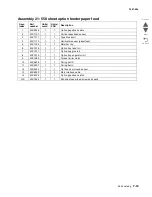
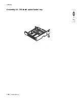
Page 484: ...7 44 Service Manual 7541 03x Go Back Previous Next Assembly 22 550 sheet option feeder tray ...


