


2-60
Service Manual
5022-
xxx
3
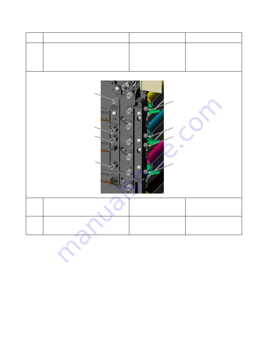
Remove HVPS. Go to
supply (HVPS) removal” on page 4-55
.
Check for continuity between black1 and
black2 on transfer contact assembly. Is
continuity present?
Go to step 4.
Replace transfer contact
assembly. Go to
contact assembly
removal” on page 4-57
4
Replace transfer contact assembly. Go to
“Transfer contact assembly removal” on
page 4-57
. Does error clear?
Problem solved.
Go to step 5.
5
Replace HVPS. Go to
supply (HVPS) removal” on page 4-55
.
Does error clear?
Problem solved.
Replace system card. Go to
“System card removal” on
page 4-47
Step
Questions / actions
Yes
No
\HOORZ
PDJHQWD
EODFN
\HOORZ
F\DQ
F\DQ
PDJHQWD
EODFN
Summary of Contents for C520 Series
Page 8: ...viii Service Manual 5022 xxx...
Page 13: ...Laser notices xiii 5022 xxx Japanese Laser Notice...
Page 14: ...xiv Service Manual 5022 xxx Korean Laser Notice...
Page 33: ...General information 1 15 5022 xxx...
Page 132: ...2 74 Service Manual 5022 xxx...
Page 202: ...4 48 Service Manual 5022 xxx 5 Remove eight screws C from system card...
Page 222: ...5 2 Service Manual 5022 xxx 7RQHU SDWFK VHQVRU 736 7RQHU OHYHO VHQVRUV...
Page 223: ...Locations and connectors 5 3 5022 xxx Motors...
Page 224: ...5 4 Service Manual 5022 xxx Printer cards...
Page 226: ...5 6 Service Manual 5022 xxx Parallel system card Legend Jxx connector Fx fuse...
Page 227: ...Locations and connectors 5 7 5022 xxx Wiring diagrams See back of manual...
Page 228: ...5 8 Service Manual 5022 xxx...
Page 230: ...6 2 Service Manual 5022 xxx...
Page 232: ...7 2 Service Manual 5022 xxx Assembly 1 CRUs 5HDU 9LHZ...
Page 234: ...7 4 Service Manual 5022 xxx Assembly 2 Covers...
Page 236: ...7 6 Service Manual 5022 xxx Assembly 3 Front...
Page 238: ...7 8 Service Manual 5022 xxx Assembly 4 Right...
Page 240: ...7 10 Service Manual 5022 xxx Assembly 5 Rear...
Page 242: ...7 12 Service Manual 5022 xxx Assembly 6 Left...
Page 244: ...7 14 Service Manual 5022 xxx Assembly 7 Top...
Page 248: ...7 18 Service Manual 5022 xxx Assembly 9 Cable Parts Packet...
Page 254: ...I 4 Service Manual 5022 xxx...


