background image

4-16

Service Manual

5060-00

x


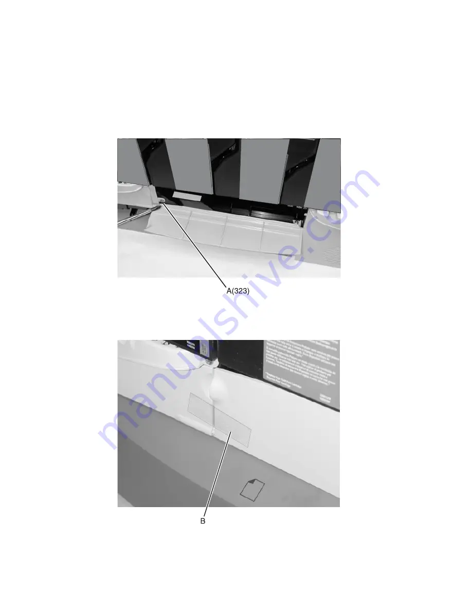
Front lower left cover removal

See 

“Front lower left cover” on page 7-3

 for part number.

1.

Remove the paper tray.

2.

Remove the front left handle cover assembly. See 

“Front left handle cover assembly removal” on 

page 4-10

.

3.

Open the paper path access door, carefully remove screw (A) type 

“323” on page 4-3

,

and close the door.

4.

Close the paper path access door and tape front jam access door (B) if tape is available, to help hold the 
door in place.
The spring loaded door is difficult to reassemble. Avoid disassembly of the door, unless you need to 
replace the paper path access door.

5.

Remove the front lower left cover with the paper path door attached.

Summary of Contents for 13P0195 - C 750dn Color Laser Printer

Page 1: ...le of contents Start diagnostics Safety and notices Trademarks Index Lexmark and Lexmark with diamond design are trademarks of Lexmark International Inc registered in the United States and or other countries Revised March 2005 ...

Page 2: ...e mail at ServiceInfoAndTraining Lexmark com Lexmark may use or distribute any of the information you supply in any way it believes appropriate without incurring any obligation to you You can purchase additional copies of publications related to this product by calling 1 800 553 9727 In other countries contact your point of purchase Lexmark Lexmark with diamond design and MarkNet are trademarks of...

Page 3: ...4 Acoustics 1 5 Environment 1 5 Print speed and performance print speed 1 6 Media specifications 1 7 Acronyms 1 13 Diagnostic information 2 1 Start 2 1 POR power on reset sequence 2 2 Symptom tables 2 3 Symptom table base printer 2 3 Symptom table 500 sheet drawer option 2 4 Symptom table HCIT 2000 sheet option 2 4 Symptom table output expander option 2 5 Symptom table 5 bin mailbox option 2 5 Sym...

Page 4: ...4 Error code 2 61 155 Error code 2 62 156 Error code 2 62 157 Error code 2 63 158 Error code 2 64 159 Error code 2 64 160 Error code 2 65 161 Error code 2 65 162 Error code 2 65 163 Error code 2 66 164 Error code 2 66 165 Error code 2 66 200 Paper jam Tray 1 2 67 200 Paper jam Options and envelope feeder 2 69 201 Paper jam 2 71 201 Paper jam 2 72 202 Paper jam 2 73 230 Paper jam 2 76 24x Paper jam...

Page 5: ...ge no image 2 139 Entire page is mostly one color Full bleed planes in one color 2 140 Missing colors Complete or partially missing color planes 2 141 Black and white only cyan magenta and yellow are missing 2 142 Light print over the entire page 2 142 All colors have light print over the entire page 2 142 One color has light print over the entire page 2 143 Low image density 2 143 Poor color alig...

Page 6: ...ss Return or Stop 3 16 TOP FINE MAR ADJ 3 16 MISC TESTS 3 16 Motor Detect 3 16 Belt Tracking ITU 4th point adjustment 3 17 PRINT TESTS 3 18 Print Tests input source 3 18 Prt Quality Pgs 3 19 Prt Line Len Pg 3 19 HARDWARE TESTS 3 19 LCD Test 3 19 Button Test 3 19 DRAM Test 3 20 CACHE Test 3 20 ROM Test 3 21 Parallel Wrap Test 3 21 Serial Wrap Test 3 22 DUPLEX TESTS 3 23 Quick Test 3 23 Top Margin 3...

Page 7: ...Removal procedures 4 5 Top cover assembly removal 4 5 Rear fan cover removal 4 8 Rear cover removal 4 8 Front right handle cover assembly removal 4 9 Front left handle cover assembly removal 4 10 Front cover assembly removal 4 10 Lower right door assembly removal 4 12 Left lower cover removal 4 13 Lower jam access door assembly removal 4 14 Redrive door removal 4 14 Paper path access door cover re...

Page 8: ...yan magenta yellow 4 64 Rear bellcrank removal black 4 66 Redrive assembly removal 4 68 Registration motor removal 4 69 RIP board removal 4 70 RIP fan removal 4 71 RIP board shield assembly removal 4 71 S2 NMS transparency sensor assembly removal 4 72 Second transfer roll removal 4 79 Transfer HVPS board removal 4 80 Transfer plate assembly 4 81 Vacuum transport belt VTB removal 4 82 Vacuum transp...

Page 9: ...per size sensing 7 18 Assembly 11 Paper feed transport 7 19 Assembly 12 Multipurpose feeder MPF 7 20 Assembly 13 500 sheet integrated tray 7 22 Assembly 14 Autocompensator assembly 7 24 Assembly 15 ITU assembly 7 25 Assembly 16 ITU drive assembly 7 26 Assembly 17 ITU loading 7 28 Assembly 18 BOR drive assembly 7 30 Assembly 19 Cartridge contact assembly 7 31 Assembly 20 Cartridge drive assembly 7 ...

Page 10: ... 29 Appendix B Print quality samples B 1 Print Menus Page one of two B 1 Print Menus Page two of two B 2 Print tests B 3 Print Quality Pages Title page total of five B 3 Print Quality Pages Page 1 total of five B 4 Print Quality Pages Page 2 total of five B 5 Print Quality Pages Page 3 total of five B 6 Print Quality Pages Page 4 total of five B 7 Registration B 8 Quick Test B 8 Alignment test pag...

Page 11: ...den Kundendienst Laserbestrahlung die die Klasse I übersteigen würde Menschen keinesfalls erreicht Avis relatif à l utilisation de laser Pour les Etats Unis cette imprimante est certifiée conforme aux provisions DHHS 21 CFR alinéa J concernant les produits laser de Classe I 1 Pour les autres pays cette imprimante répond aux normes IEC 60825 1 relatives aux produits laser de Classe I Les produits l...

Page 12: ...potássio de 5 milliwatts operando numa faixa de comprimento de onda entre 770 e 795 nanómetros O sistema e a impressora laser foram concebidos de forma a nunca existir qualquer possiblidade de acesso humano a radiação laser superior a um nível de Classe I durante a operação normal a manutenção feita pelo utilizador ou condições de assistência prescritas Laserinformatie De printer voldoet aan de ei...

Page 13: ...ör att någon person utsätts för laserstrålning över Klass I nivå vid normal användning underhåll som utförs av användaren eller annan föreskriven serviceåtgärd Laser melding Skriveren er godkjent i USA etter kravene i DHHS 21 CFR underkapittel J for klasse I 1 laserprodukter og er i andre land godkjent som et Klasse I laserprodukt i samsvar med kravene i IEC 60825 1 Klasse I laserprodukter er ikke...

Page 14: ...xiv Service Manual 5060 00x ...

Page 15: ...Laser notice xv 5060 00x ...

Page 16: ...xvi Service Manual 5060 00x ...

Page 17: ...signes d entretien et de réparation de ce produit s adressent uniquement à un personnel de maintenance qualifié Le démontage et l entretien de ce produit pouvant présenter certains risques électriques le personnel d entretien qualifié devra prendre toutes les précautions nécessaires ATTENTION Ce symbole indique la présence d une tension dangereuse dans la partie du produit sur laquelle vous travai...

Page 18: ...bre el mantenimiento de este producto está dirigida exclusivamente al personal cualificado de mantenimiento Existe mayor riesgo de descarga eléctrica y de daños personales durante el desmontaje y la reparación de la máquina El personal cualificado debe ser consciente de este peligro y tomar las precauciones necesarias PRECAUCIÓN este símbolo indica que el voltaje de la parte del equipo con la que ...

Page 19: ...roducte està orientada exclusivament a professionals i no està destinada a ningú que no ho sigui El risc de xoc elèctric i de danys personals pot augmentar durant el procés de desmuntatge i de servei d aquest producte El personal professional ha d estar ne assabentat i prendre les mesures convenients PRECAUCIÓ aquest símbol indica que el voltatge de la part de l equip amb la qual esteu treballant ...

Page 20: ...nd removing and installing FRUs 5 Connector locations uses illustrations to identify the connector locations and test points on the printer 6 Preventive maintenance contains the lubrication specifications and recommendations to prevent problems 7 Parts catalog contains illustrations and part numbers for individual FRUs Appendix A contains service tips and information Appendix B contains representa...

Page 21: ...t network configurations requiring Ethernet Token Ring LocalTalk serial infrared or additional parallel ports The printer has flexible paper handling It supports a wide variety of paper sizes and has a standard multipurpose feeder that makes it easy to print on envelopes transparencies labels card stock and non standard size paper You can add up to three optional drawers to the base printer which ...

Page 22: ...e part Each of the five bins supports approximately 100 pages of 20 lb paper Only one output option above the printer is supported Finisher offers stapling hole punching offset stacking and an additional output bin Two models are available Hole punching for 2 3 or 4 hole left edge is available The single staple position is the upper left corner The finisher supports up to 3 000 sheets of non stapl...

Page 23: ...th Height Weight Printer Lexmark C750 n 23 8 in 604 5 mm 18 5 in 469 9 mm 20 8 in 528 3 mm 105 lb 47 7 kg Lexmark C750dn inc Duplex Opton 23 8 in 604 5 mm 18 5 in 469 9 mm 24 3 in 617 2 mm 118 lb 53 8 kg Options Duplex Option 23 8 in 604 5 mm 18 5 in 469 9 mm 3 5 in 88 9 mm 13 5 lb 6 1 kg 2 000 Sheet Tray 26 in 660 4 mm 23 8 in 604 5 mm 15 4 in 391 2 mm 49 lb 22 3 kg Output Expander 14 5 in 368 3 ...

Page 24: ...All 20 in 508 mm Rear All 12 in 304 8 mm Top C750 n 42 in 1 066 8 mm 2 C750dn 34 in 863 6 mm 2 1 Allow 1 219 2 mm 48 in clearance to the right if you are adding a finisher 2 Allow clearance above the printer front door clearance and for adding options such as additional input drawers output expander or 5 bin mailbox Upgrade kit Description Part number 115 V web oiler upgrade kit 12G6514 220 V web ...

Page 25: ...mperature 80 1 F 26 7 C Altitude 10 000 ft 0 to 3 048 meters Atmospheric pressure 74 6 kPa Ambient operating environment Temperature 60 to 90 F 15 6 to 32 2 C Relative humidity 8 to 80 Storage and shipping packaged printer with or without print cartridge Temperature 40 to 110 F 40 to 43 3 C Print cartridge Temperature 40 to 110 F 40 to 43 3 C In some cases performance specifications such as paper ...

Page 26: ...n letter size paper The test job consists of the character A followed by a form feed single page job The first copy time is defined as the elapsed time from hitting enter on the PC keyboard to the page exiting to the output bin All tests will pick paper from the primary input tray and the page will exit into the primary output bin Processor 350 MHz Duty cycle Up to 60K page maximum one time usage ...

Page 27: ...ard disk 1 Additional memory may be required for printing complex pages or full page high resolution images in 1200 image quality at rated speeds Media specifications Media type DRAM memory Lexmark C750 n Lexmark C750dn Standard 64MB 128MB Maximum 512MB 512MB Media type 500 Sheet input Multi purpose tray 2 000 Sheet drawer Duplex Standard output 5 Bin Mailbox Output Expander Finisher to staple hol...

Page 28: ...6 7 Folio 8 5 in x 13 in 216 mm x 330 mm 4 x x x x x x x 5 6 7 Legal 8 5 in x 14 in 216 mm x 256 mm x x x x x x x x 5 6 7 Executive 7 25 in x 10 5 in 184 mm x 267 mm x x x x x x x x 6 7 Universal1 5 5 x 8 27 in to 8 5 x 14 in 139 7 x 210 mm to 215 9 x 355 6 mm x x x x x 2 75 x 5 in to 8 5 x 14 in 69 85 x 127 mm to 229 x 355 6 mm x x 5 83 x 7 17 in to 8 5 x 14 in 148 x 182 mm to 215 9 x 355 6 mm x ...

Page 29: ... page is formatted for 8 5 x 14 in 215 9 x 355 6 mm unless the size is specified in the software application 4 Statement and Folio are supported as standard size through software only Tray size sensing must be turned off before this standard size is visible in the paper size menu on the operator panel 5 2 hole punch is supported 6 3 hole punch is supported 7 4 hole punch is supported Media size su...

Page 30: ...ms Pressure sensitive area c 140 to 175 g m2 Paper base grain long 20 to 36 lb bond 75 to 135 g m2 Multipurpose feeder Paper b f Xerographic or business paper 16 to 19 9 lb bond 60 to 74 9 g m2 grain long 20 to 47 lb bond 75 to 176 g m2 grain long Specialty papers Gloss book 60 to 120 lb book 88 to 176 g m2 grain long Gloss cover 60 to 65 lb cover 162 to 176 g m2 grain long Card stock upper limit ...

Page 31: ...n on whether your vinyl label converter has passed Lexmark s criteria Refer to the Card Stock and Label Guide for more details i Lexmark transparency numbers 12A5940 and 12A5941 are supported from the standard tray optional 500 sheet trays and the multipurpose feeder j Lexmark transparency numbers 12A5150 and 12A5151 are supported from the multipurpose feeder only Media Weight Standard output bin ...

Page 32: ...tive humidity and is not supported in duplex c Pressure sensitive area must enter the printer first d 100 cotton content maximum weight is 24 lb bond 28 lb envelopes are limited to 25 cotton content e 28 lb bond envelopes are limited to 25 cotton content f The duplex option supports the same types and weights as the printer except 16 to 19 9 lb 60 to 74 9 g m2 grain long paper transparencies label...

Page 33: ...ed Emission of Radiation LCD Liquid Crystal Display LED Light Emitting Diode LVPS Low Voltage Power Supply M Magenta MPF Multipurpose Feeder MROM Masked Read Only Memory MS Microswitch NVRAM Nonvolatile Random Access Memory OEM Original Equipment Manufacturer OPT Optical Sensor PC Photoconductor pel Picture element POR Power On Reset POST Power On Self Test PSD Position Sensing Device PWM Pulse Wi...

Page 34: ...1 14 Service Manual 5060 00x ...

Page 35: ...o repair a printer see the following topics POR power on reset sequence on page 2 2 Symptom table base printer on page 2 3 Symptom table 500 sheet drawer option on page 2 4 Symptom table HCIT 2000 sheet option on page 2 4 Symptom table output expander option on page 2 5 Symptom table 5 bin mailbox option on page 2 5 Symptom table finisher option on page 2 5 Error code table on page 2 6 Sub error c...

Page 36: ...ront panel LED blinks 19 Redrive exit roller turns 20 Any cartridge errors are posted such as a defective cartridge Lexmark Return Program information or missing cartridge 21 Any applicable maintenance messages display such as 80 Fuser Maintenance or 83 Maintenance 22 One of the toner low messages appears when applicable 88 yellow Toner Low 88 Magenta Toner Low 88 Cyan Toner Low or 88 Black Toner ...

Page 37: ...only If the printer is set up correctly check the black retract motor and gears for correct operation If the gears are operating correctly go to Black only retract BOR service check on page 2 117 Print quality 100 single color printed All black print All cyan print All magenta print All yellow print Go to Entire page is mostly one color Full bleed planes in one color on page 2 140 Print quality bl...

Page 38: ...position Go to Tray x autocompensator fails to retract stays in down position on page 2 109 Paper Low message appears when adequate paper is installed tray x Go to The printer does not detect paper low in Tray x when adequate paper is installed in the tray on page 2 109 Paper Out message appears when adequate paper is installed tray x Go to The printer does not detect paper out in tray x when adeq...

Page 39: ...eed into the 5 Bin mailbox bin selected 271 Paper Jam Check Bin 1 message on page 2 106 Paper Jam 271 Check Bin 1 message appears Go to Paper does not feed into the 5 Bin mailbox bin selected 271 Paper Jam Check Bin 1 message on page 2 106 Ready and Bin x Full message appears Go to Ready Bin x Full message may be able to clear message and paper feeds into bin selected on page 2 106 Bin is full but...

Page 40: ... does not fix the problem replace the engine board See Engine board removal on page 4 29 910 Trans Sensor Tray 1 Transparency Sensor Error replace Tray 1 autocompensator assembly See Autocompensator pick assembly removal on page 4 17 If this does not fix the problem replace the engine board See Engine board removal on page 4 29 911 Trans Sensor Tray 2 Transparency Sensor Error replace Tray 2 trans...

Page 41: ... problem replace the engine board See Engine board removal on page 4 29 940 TMC Error Cyan Cyan toner metering cycle TMC switch failure go to 940 Error code on page 2 93 941 TMC Error Magenta Magenta toner metering cycle TMC switch failure go to 941 Error code on page 2 95 942 TMC Error Yellow Yellow toner metering cycle TMC switch failure go to 942 Error code on page 2 97 943 TMC Error Black Blac...

Page 42: ...e check the following If installed check network card for correct installation If correctly installed replace the network card If a network card is not installed replace the RIP board 976 Standard Network Unrecoverable software or error in network port Network card x If unable to clear the error message check the following If installed check network card for correct installation If correctly insta...

Page 43: ...n equipment check condition has occurred in the specified device but the device is unable to identify the exact component failure Note device can be one of the following Duplex option Tray x where x 1 2 3 4 or 5 Output bin x where x 1 2 3 or 6 Note This message is used for single bin output devices Output bin x to y where x 1 to 5 Note This message is used for multiple bin output devices Go to the...

Page 44: ... go to Printhead diagnostics on page 3 1 Note Do not adjust or replace any printhead before performing the checks in Printhead diagnostics on page 3 1 109 Printhead Error Black printhead lost Hsync Check for the correct installation of the all the cables to the RIP board assembly and to the printhead assembly J9 J10 and J11 on the RIP board Go to RIP board on page 5 14 If the cables are connected ...

Page 45: ...sembly J2 J3 and J4 on the RIP board Go to RIP board on page 5 14 If the cables are connected correctly to the RIP board and to the printhead assembly go to Printhead diagnostics on page 3 1 Note Do not adjust or replace any printhead before performing the checks in Printhead diagnostics on page 3 1 114 Printhead Error A black printhead servo error has been detected Verify all packing material has...

Page 46: ...cs on page 3 1 120 Fuser Error Wrong fuser lamp hot roll Replace with correct lamp Go to 120 Error code on page 2 44 121 Fuser Error Wrong fuser lamp BUR Replace with correct lamp Go to 121 Error code on page 2 45 122 Fuser Error Fuser below temperature when printing hot roll Go to 122 Error code on page 2 46 123 Fuser Error Fuser below temperature when printing BUR Go to 123 Error code on page 2 ...

Page 47: ...l on page 4 69 If this does not fix the problem replace the engine board See Engine board removal on page 4 29 142 Motor DC pick motor over speed registration motor replace the registration motor assembly See Registration motor removal on page 4 69 If this does not fix the problem replace the engine board See Engine board removal on page 4 29 143 Motor DC pick motor no encoder feedback registratio...

Page 48: ...otor Magenta cartridge motor lost lock Go to 157 Error code on page 2 63 158 Motor Cyan cartridge motor lost lock Go to 158 Error code on page 2 64 159 Motor Yellow cartridge motor lost lock Go to 159 Error code on page 2 64 160 Motor ITU belt BLDC motor mfg unknown Go to 160 Error code on page 2 65 161 Motor Fuser drive BLDC motor mfg unknown Go to 161 Error code on page 2 65 162 Motor Black cart...

Page 49: ...s on page 3 1 176 Motor Mirror motor lost lock yellow Go to Printhead diagnostics on page 3 1 Note Do not adjust or replace any printhead before performing checks in Printhead diagnostics on page 3 1 180 PSD Error PSD sensor error black Update machine code Run a Line Length test page See Prt Line Len Pg on page 3 19 If the problem persists go to Printhead diagnostics on page 3 1 181 PSD Error PSD ...

Page 50: ... sensor out of range process direction yellow Update the machine code Run a Line Length test page See Prt Line Len Pg on page 3 19 If the problem persists go to Printhead diagnostics on page 3 1 192 PSD Error No EOS reading black Update the machine code Run a Line Length test page See Prt Line Len Pg on page 3 19 If the problem persists go to Printhead diagnostics on page 3 1 193 PSD Error No EOS ...

Page 51: ...the timeout period 2D 09 Paper jam detected The fuser exit sensor did not deactivate during the timeout period 2D 0A Paper jam detected A paper jam detected in the Duplex Option 2D 0B Paper jam detected A paper jam detected in Tray 2 2D 0C Paper jam detected A paper jam detected in Tray 3 2D 0D Paper jam detected A paper jam detected in Tray 4 2D 0E S2 sensor was not made within timeout period sou...

Page 52: ...ion 2D 2D Duplex input motor error detected the engine detected a PWM error 2D 2E Duplex input motor error detected the engine detected a motor encoder error 2D 2F Duplex reversing motor error detected the engine detected a stall condition 2D 30 Duplex reversing motor error detected the engine has detected a PWM error condition 2D 31 Duplex reversing motor error detected the engine detected a moto...

Page 53: ...on Motor Encoder error detected 2D 4B Autocompensator motor encoder error detected when picking media from the MPF 2D 4C Autocompensator motor encoder error detected when picking media from Tray 1 2D 4E Output expander sensor was not activated by the media 2D 4F Topmost output option sensor obstructed 2D 50 5 Bin mailbox pass thru sensor was not deactivated by the previous page or not activated by...

Page 54: ...ogram a non network printer or a non network file was used to program a network printer P109 Package size error An update file was used to program the printer but the package did not fit within the space allocated in the Master Boot Record P112 Invalid DLE An upddle fls file was used to update the DLE code on printer with a firmware card installed but the DLE was not found on the firmware card P20...

Page 55: ...ges Collation Separator Sheets Separator Source Hole Punch Offset Pages Staple Job Staple Prime Src Multipage Print Multipage Order Multipage View Multipage Border Color Menu Color Correction Manual Color Print Mode Print Resolution Toner Darkness Job Menu Cancel Job Reset Printer Print Buffer Cancel Fax Confidential Job Held Jobs Reset Active Bin Utilities Menu Color Adjust Color Samples Print De...

Page 56: ...algorithm that produces brighter more saturated colors May be selected for all incoming color formats sRGB Display Applies color correction to produce output that approximates the colors displayed on a computer monitor sRGB Vivid Increases color saturation for the sRGB Display color correction Off No color correction is implemented RGB Text Vivid sRGB Display sRGB Vivid Off RGB Graphics Vivid sRGB...

Page 57: ... manually relinearize the color tables adjusting for variations in output that occur as a result of environmental conditions Color Samples To assist in selecting colors used by certain applications Defragment Flash To retrieve storage area lost when resources are deleted from flash memory Warning Do not turn off the printer while the flash is defragmenting Yes Printer transfers all resources store...

Page 58: ...job statistics stored on the hard disk or to clear all statistics on the disk Print Prints all statistics available for the most recent print jobs Clear Deletes all accumulated job statistics from the hard disk Print Demo To view a list of the demo files available in printer memory in flash memory and on optional hard disk Print Directory To print a list of all the resources stored in flash memory...

Page 59: ... fuser Open the right door to access the jam area If sheets have been accumulated to be stapled or offset when the jam occurred the printer alternately flashes the primary and secondary messages to indicate that all accumulated sheets not be removed during the jam clearing procedure If the problem persists go to 201 Paper jam on page 2 71 Secondary When this message is displayed do not remove accu...

Page 60: ...inted after the jam will not be stapled 24x Paper Jam Clear Paper Path Leave Job in Finisher Primary Media is jammed around Tray x Tray x 2 through 4 and applies to both a 500 Tray and HCIT tray Try opening Tray x If the tray is difficult to remove then you may need to remove the tray above or below Tray x to remove the jam If sheets have been accumulated to be stapled or offset when the jam occur...

Page 61: ...s Also if the accumulated sheets are removed the portion of the job printed after the jam will not be stapled 272 Paper Jam Clear Paper Path Leave Job in Finisher Primary Media is jammed in output bin x Open the door of output bin x to access the jam If sheets have been accumulated to be stapled or offset when the jam occurred the printer alternately flashes the primary and secondary messages to i...

Page 62: ...is displayed if the accumulated sheets are removed the printer will not reprint these sheets Also if the print job is completed the portion of the job printed after the jam will not be stapled 202 Paper Jam Clear Paper Path Leave sheets in Finisher area 5 Primary Media has jammed at the fuser Open the printer right door to access the jam area Secondary If sheets have been accumulated to be stapled...

Page 63: ... If sheets have been accumulated to be stapled when the jam is detected the printer alternately flashes the primary and secondary messages indicating the accumulated sheets should not be removed during jam clearing Note When the secondary message is displayed if the accumulated sheets are removed the printer will not reprint these sheets Also if the print job is completed the portion of the job pr...

Page 64: ... the jam will not be stapled 282 Staple Jam Check Stapler 283 Staple Jam Check Stapler Remove Job from Finisher These messages are displayed when the stapler device detects a paper jam 282 Staple Jam indicates that a staple jam has been detected during normal stapler operation such as when printing and stapling jobs 283 Staple Jam indicates that a staple jam has been detected during a priming oper...

Page 65: ...s when Performing Self Test displays 4 Select Calibrate Trays 5 Select Tray x from the menu 6 The display prompts load paper if necessary 7 Load paper 8 Press Go Calibrating Tray x is displayed 9 Repeat for any other trays that might need to be calibrated 10 Exit Configuration Menu Change Cartridge Color Invalid Refill This message is displayed when the printer has detected a refilled Lexmark Retu...

Page 66: ...ion removed If the problem continues turn the printer off and back on If the message continues to be displayed turn the printer off remove the option and call for service Close Door This message is displayed when the printer upper front cover door is open Close the upper front cover door Close Finisher Door This message is displayed when the finisher Option top cover is open Close the finisher top...

Page 67: ... staples The Staples Empty warning appears on the status line and Load Staples may immediately appears Load Staples This message is displayed when the Staples Empty Alarm is activated and there are no staples in the staple unit or the staple unit is not installed This message appears Prior to printing the first page of a batch of pages that are to be stapled or During the printing of a batch of pa...

Page 68: ...e reinstallation of the option to print a page which has been formatted by an install Tray x interpreter prior to removal of the option or Cancel Job Bin x x 1 2 or 3 Tray x x 2 3 4 or 5 Duplex The following actions can be taken Insert the requested option or Press Menu or Menu to access the Busy Waiting Menu Group The following functions are available using the Busy Waiting Menu Cancel Job Reset ...

Page 69: ...detects a media mismatch feeding from the MPF Primary Message Incorrect media detected Secondary Message type Bond Cardstock Colored Labels Envelopes Letterhead Plain Preprinted Transparency or Glossy size Letter Legal B5 A4 Exec Univ A5 A3 11x17 Folio Stmt 73 4 9 10 DL C5 B5 or other The following actions can be taken Replace the media in the MPF with the requested media and press Go or Press Men...

Page 70: ...e job or Press Menu or Menu to access the Busy Waiting Menu The following functions are available using the Busy Waiting Menu Cancel Job Reset Printer Reset Active Bin Check Supply Levels Note Menu Lockout does NOT prevent access to the Busy Waiting Menu 37 Insufficient Defrag Memory This message is displayed when insufficient printer memory is available to perform Flash Memory Defragment operatio...

Page 71: ... cannot be accessed 38 Memory Full This message is displayed when the printer is processing an incoming job and there is not enough memory available to continue processing the job The following actions can be taken You may want to determine how to make more memory available to your print job by Deleting fonts macros and other data in RAM Simplify your print job Install additional memory Press Go t...

Page 72: ... Par ENA Connection Lost This message is displayed when the printer detects during POST that the connection to an ENA has been lost Once a connection is initially established a printer setting is modified to 54 Par x ENA to note a connection exists Each time the power is cycled on the connection is lost 54 Std Network Software Error This message is displayed when the RIP software detects that a ne...

Page 73: ...e parallel port is discarded Press Menu to access the Busy Waiting Menu The following functions may be available Reset Printer Reset Active Bin Check Supply Levels Note Menu Lockout does NOT prevent access to the Busy Waiting Menu 56 Standard USB Port Disabled 56 USB Port x Disabled These messages may appear when data is sent to the printer across the USB port but the port is disabled Note Once th...

Page 74: ...hen the printer detects a defective disk This error may occur at power on or during disk format and write operations Press Go to clear the message The disk is marked as defective and normal printer operation continues Disk operations are not allowed with a defective disk and the Format Disk menu item is not shown 62 Disk Full This message is displayed when there is not enough free space on the dis...

Page 75: ...s message is displayed when the waste container is nearly full Press Go Nearly Full appears in the Supplies Menu 84 Replace Oiler This message is displayed when the web oiler is exhausted or missing Replace the web oiler See Fuser web oiler motor assembly removal on page 4 35 84 Oiler Nearly Exhausted This message is displayed when the Wed Oiler is nearly exhausted Press Go to continue or replace ...

Page 76: ... on a solid flat surface Is the printer setting on a solid flat surface Go to step 3 Go to step 4 3 Inform the customer that the printer must be setting on a solid flat surface or install the printer on a solid flat surface as available Recheck the printer to see if a 100 ITU error is still displayed Is a 100 ITU error still displayed Go to step 4 Problem solved 4 Make sure the ITU cleaner gear A ...

Page 77: ... 8 Remove the ITU and check the ITU belt position If the belt has shifted front to rear it should be replaced The belt must not shift more than 4 mm in either direction Check by making the measurements as shown The lower limit is 3 1 mm the high limit is 8 1 mm and the optimum position is 5 6 mm Has the ITU belt shifted front to rear Replace the ITU assembly See ITU assembly removal on page 4 37 G...

Page 78: ...n the engine board Is the cable correctly installed Go to step 13 Install the cable correctly 13 Make sure the ITU autoconnect connector in the printer is seated correctly in the connector plate Is the connector seated correctly Go to step 14 Install the connector cable correctly 14 Check continuity of the ITU autoconnect cable Is there continuity Replace the following FRUs in the order shown 1 IT...

Page 79: ...moval on page 4 31 Step Action and questions Yes No 1 Is the correct fuser assembly installed in the printer Go to step 2 Install the correct fuser assembly See Fuser assembly removal on page 4 31 2 Is the correct fuser backup roll lamp installed in the fuser assembly Go to step 3 Install the correct fuser backup lamp 3 Check for continuity between pins 2 and 5 on the AC fuser connector located on...

Page 80: ... 38 3 Engine board See Engine board removal on page 4 29 124 Error code Hot fuser The printer detects a problem with the fuser running over temperature or the hot roll fuser lamp has been on too long A problem may exist in the fuser assembly with the hot roll bearings the hot roll thermistor or other hot roll parts The LVPS or engine board assembly can also be failing Step Action and questions Yes...

Page 81: ...ter on and measure the voltage on connector J10 12 on the engine board The voltage should measure approximately 0 13 V dc to 0 64 V dc as the hot roll lamp turns on and off Is the voltage correct Replace the fuser assembly See Fuser assembly removal on page 4 31 Replace the engine board assembly See Engine board removal on page 4 29 Step Action and questions Yes No 1 Turn the printer on and allow ...

Page 82: ...tor See Engine board on page 5 7 The voltage should measure approximately 3 3 V dc Is the voltage correct Replace the fuser assembly See Fuser assembly removal on page 4 31 Replace the LVPS See Low voltage power supply LVPS removal on page 4 38 Step Action and questions Yes No 1 Turn the printer on to allow it to reach Ready Note The printer may not complete POR and continue to display a 128 error...

Page 83: ...e the fuser assembly from the printer and measure the voltage on connector J10 7 on the engine board The voltage should measure approximately 3 3 V dc Is the voltage correct Go to step 2 Replace the engine board assembly See Engine board removal on page 4 29 2 Measure the voltage on pin 7 of the DC control connector on the LVPS The voltage should measure approximately 3 3 V dc Is the voltage corre...

Page 84: ... Use caution when handling the lamp as it is easily broken Check continuity of the lamp Is there continuity Replace the fuser assembly See Fuser assembly removal on page 4 31 Replace the lamp 5 Reinstall the fuser assembly Watch to see if the lamps turn on and off as the lap heats up Do the lamps turn on and off Go to step 6 Replace the LVPS assembly See Low voltage power supply LVPS removal on pa...

Page 85: ... Install the lamp correctly 4 Carefully remove the lamp from the fuser assembly being careful to only handle the lamp by the ceramic end pieces and not by the glass envelope Warning Use caution when handling the lamp as it is easily broken Check the continuity of the backup roll lamp Is there continuity Replace the fuser assembly See Fuser assembly removal on page 4 31 Replace the backup roll lamp...

Page 86: ...uity of the hot roll lamp by measuring between pins 1 and 2 on the AC fuser connector on the fuser assembly Is there continuity Go to step 5 Go to step 3 3 Make sure the hot roll lamp is installed correctly Is the lamp installed correctly Go to step 4 Install the hot roll lamp correctly 4 Carefully remove the lamp from the fuser assembly being careful to only handle the lamp by the ceramic end pie...

Page 87: ...tage on connector J10 12 on the engine board The voltage should measure approximately 0 13 V dc to 0 64 V dc as the backup roll lamp turns on and off Is the voltage correct Replace the fuser assembly See Fuser assembly removal on page 4 31 Go to step 2 2 Remove the fuser from the printer Check continuity of the hot roll lamp by measuring between pins 2 and 5 on the AC fuser connector on the fuser ...

Page 88: ... Engine board removal on page 4 29 7 Measure the voltage on pin 7 of the fuser DC control connector The voltage should measure approximately 3 3 V dc Is the voltage correct Replace the fuser assembly See Fuser assembly removal on page 4 31 Replace the LVPS assembly See Low voltage power supply LVPS removal on page 4 38 Step Action and questions Yes No 1 Turn the printer on open the right side fuse...

Page 89: ...d observe the backup roll lamp to see if it turns on and off You may have to observe the lamp for a few minutes to see if it turns on and off Does the lamp turn on and off Go to step 2 Replace the LVPS assembly See Low voltage power supply LVPS removal on page 4 38 2 Turn the printer on Measure the voltage on engine board connector J10 12 The voltage should be approximately 0 13 V dc to 0 64 V dc ...

Page 90: ...the printer Measure the voltage at the DC fuser control connector pins 2 and 9 The voltage should measure approximately 5 V dc Is the voltage correct Replace the fuser assembly See Fuser assembly removal on page 4 31 Replace the LVPS assembly See Low voltage power supply LVPS removal on page 4 38 6 Check for correct installation of the fuser drive motor cable to connector J8 on the engine board Is...

Page 91: ... the ITU drive motor cable Do you measure continuity Go to step 4 Replace the ITU drive motor cable 4 ITU drive motor voltage check measure the voltage on connector J64 on the engine board The voltages are approximately values Voltages motor not running Are the voltages correct Replace the drive motor Go to step 5 5 ITU motor drive assembly remove the ITU assembly Manually turn the motor The gears...

Page 92: ...ing FRUs in the order shown 1 Fuser drive assembly removal on page 4 33 2 Engine board removal on page 4 29 Step Actions and questions Yes No 1 Check the black cartridge drive motor cable connection to J64 on the engine board Is the cable installed correctly Go to step 2 Install the cable correctly 2 Check the black cartridge drive motor cable connection to the black cartridge drive motor card Is ...

Page 93: ...ridge drive motor card Is the cable installed correctly Go to step 3 Install the cable correctly 3 Check continuity of the magenta cartridge drive motor cable Is there continuity Go to step 4 Replace the magenta cartridge assembly cable 4 Replace the magenta cartridge drive assembly Perform the Motor Detect on page 3 16 Does this fix the problem Problem solved Go to step 5 5 Replace the engine boa...

Page 94: ...cable connection to J47 on the engine board Is the cable installed correctly Go to step 2 Install the cable correctly 2 Check the yellow cartridge drive motor cable connection to the yellow cartridge drive motor card Is the cable installed correctly Go to step 3 Install the cable correctly 3 Check continuity of the yellow cartridge drive motor cable Is there continuity Go to step 4 Replace the yel...

Page 95: ...uity of the ITU drive motor cable Do you measure continuity Go to step 4 Replace the ITU drive motor cable 4 ITU drive motor voltage check measure the voltage on connector J64 on the engine board The voltages are approximately values Voltages Motor not running Are the voltages correct Replace the drive motor Go to step 5 5 ITU motor drive assembly remove the ITU assembly Manually turn the motor Th...

Page 96: ...ge 4 33 2 Engine board See Engine board removal on page 4 29 Replace the fuser drive assembly See Fuser drive assembly removal on page 4 33 Replace the fuser top duct See Fuser top duct removal on page 4 34 Step Actions and questions Yes No 1 Check the black cartridge drive motor cable connection to J64 on the engine board Is the cable installed correctly Go to step 2 Install the cable correctly 2...

Page 97: ... the engine board Is the cable installed correctly Go to step 2 Install the cable correctly 2 Check the magenta cartridge drive motor cable connection to the magenta cartridge drive motor card Is the cable installed correctly Go to step 3 Install the cable correctly 3 Check continuity of the magenta cartridge drive motor cable Is there continuity Go to step 4 Replace the magenta cartridge assembly...

Page 98: ... motor card Is the cable installed correctly Go go step 3 Install the cable correctly 3 Check continuity of the cyan cartridge drive motor cable Is there continuity Go to step 4 Replace the cyan cartridge assembly cable 4 Replace the cyan cartridge drive assembly Perform Motor Detect on page 3 16 Does this fix the problem Problem solved Go to step 5 5 Replace the engine board Does this fix the pro...

Page 99: ...tor Detect on page 3 16 Is error code 160 still shown Call your next level support Problem solved Step Action and questions Yes No 1 Fuser drive motor assembly error code 161 indicates that an incorrect motor is detected Replace the fuser drive assembly See Fuser drive assembly removal on page 4 33 Note Anytime the fuser drive assembly is replaced perform the Motor Detect on page 3 16 Does error c...

Page 100: ...hat an incorrect motor is detected Replace the magenta cartridge drive assembly See Cartridge drive assembly removal on page 4 26 Perform the Motor Detect on page 3 16 Does the printer display error code 163 Go to step 2 Problem solved 2 Reflash the NVRAM on the engine board Does error code 163 continue Call your next level support Problem solved Step Actions and questions Yes No 1 Replace the cya...

Page 101: ...reak in time on page 2 69 Step Action and questions Yes No 1 Is sensor flag obstructed by paper debris out of position or broken Clear obstruction and reinstall or replace flag Go to step 2 2 Perform the BASE SENSOR TEST on page 3 29 Do both sensor pass the test Problem solved Go to step 3 3 Is the inner deflector out of place causing sensor flag to bind Install inner deflector properly Go to step...

Page 102: ...to step 3 3 Check for obstructions in the paper path Is the paper path obstructed Clear the obstruction Go to step 4 4 Is the inner deflector out of position Correct the deflector position Go to step 5 5 Is the autocompensator damaged or defective Go to Autocompensa tor service check on page 2 114 Go to step 6 6 Perform the BASE SENSOR TEST on page 3 29 on the S2 sensor Does the S2 sensor pass the...

Page 103: ...er jammed at the second transfer roll Clear the jam Call your next level of support Step Action and questions Yes No 1 Does media feed correctly from Tray 1 Go to step 2 Go to 200 Paper jam Tray 1 on page 2 67 2 Check tray 2 or the envelope feeder if installed for proper media loading Media should be fanned before loading and must lay flat in the tray Is the media loaded properly Go to step 3 Load...

Page 104: ...heet option or envelope option on page 2 69 3 Check tray 1 pass thru for damage or obstruction Is the pass thru obstructed or damaged Clear the obstruction Repair or replace the duplex option Step Action and questions Yes No 1 Make sure the media installed in the tray meets specifications Note The HCIT only supports paper Does the media meet specifications Go to step 2 Inform customer that media d...

Page 105: ...o step 5 Perform the following in order 1 Reseat the connector J10 on the engine board 2 Replace the fuser See Fuser assembly removal on page 4 31 3 Replace the LVPS See Low voltage power supply LVPS removal on page 4 38 4 Replace the engine board See Engine board removal on page 4 29 5 Check the vacuum transport belts VTB for motion Observe the belt through the front door Are the belts on the VTB...

Page 106: ...r torn belts excessive toner buildup or damage to the transport assembly especially to the transport drive gear Are there broken or damaged parts in the vacuum transport assembly Replace the vacuum transport assembly Go to step 5 5 Make sure that the vacuum transport assembly drive gear meshes correctly with drive gear on the fuser drive assembly Do the gears mesh correctly Go to step 6 Make sure ...

Page 107: ...ely Go to step 4 Replace the fuser See Fuser assembly removal on page 4 31 4 Reinstall the fuser and perform the BASE SENSOR TEST on page 3 29 for the fuser exit sensor Note Use a spring hook to actuate the flag Does the fuser exit sensor pass Got to step 5 Perform the following in order 1 Reseat the connector J10 on the engine board 2 Replace the fuser See Fuser assembly removal on page 4 31 3 Re...

Page 108: ...el to check if the jam occurred at duplex entry edge guide Did the jam occur at the duplex entry edge guide Replace the duplex option Go to step 9 9 If the duplex option is in use check the actuator button See Duplex option deflector button replacement on page 29 Should the actuator button be replaced Replace the button Go to step 10 10 If the finisher option is in use refer to the finisher manual...

Page 109: ...ions Yes No 1 Check of mechanical drive components Check the output expander drive belt to make sure it is installed on the drive pulley and belt idler pulley Check the belt tension spring to make sure it is not loose or broken Are there any problems with these parts Repair or replace as necessary Go to step 2 2 Check of mechanical linkage DC motor drive assembly Check to see if the DC motor is fu...

Page 110: ...door and check that the diverter operates freely Does the diverter operate freely Go to step 5 Replace the fuser assembly See Fuser assembly removal on page 4 31 5 Close the redrive door and check that the diverter operates freely Does the diverter operate freely Go to step 6 Replace the redrive door See Redrive door removal on page 4 14 6 Check that the diverter actuator link is not binding or da...

Page 111: ...plex system board Are the cables correctly connected Repair or replace the duplex option Correctly connect the cables Paper jam code Tray identification Problem related to the following option or tray depending on installed configuration 241 Tray 1 Internal 500 sheet tray 242 Tray 2 500 sheet tray option 243 Tray 3 500 sheet tray option or 2000 sheet HCIT option 244 Tray 4 500 sheet tray option St...

Page 112: ...ion by running the Tray x sensor test from the Diagnostics Menu See Sensor Test on page 3 24 Does the pass thru sensor operate correctly Check for any obstructions that might catch the media and create a paper jam Go to step 10 10 Make sure the pass thru sensor is correctly connected to the Tray x system board Is the sensor cable connected correctly Replace the FRUs in the following order 1 Pass t...

Page 113: ...he tray Does the paper feed from the paper tray Go to step 14 Go to step 4 4 Using the standalone feeding operation test observe the registration motor the registration motor is the motor at the top of the feed assembly Does the motor turn Go to step 5 Go to step 6 5 Does the pick motor the lower motor in the feed unit assembly turn Go to step 8 Go to step 7 6 Check the registration motor cable to...

Page 114: ...the system board Is the cable connected correctly Go to step 13 Install the cable correctly 13 Is the registration home sensor operating correctly Replace the following FRUs in the order shown 1 HCIT system board 2 Feed unit assembly Replace the following FRUs in the order shown 1 Registration sensor 2 HCIT system board 14 Use the standalone feeding operation test to determine where the paper jams...

Page 115: ...Diagnostic information 2 81 5060 00x Printer configuration diagrams for 24x paper jams ...

Page 116: ...ght The leading edge of the media should be sitting on the friction buckler Is the media correctly loaded Go to step 5 Properly load the media 5 Open the MPF to the horizontal position and check the paper path for obstructions Is the paper path obstructed Clear the obstruction Go to step 6 6 Raise the pick roll off the media and test the MPF Does the pick roll turn Go to step 8 Go to step 7 7 Open...

Page 117: ...o step 2 2 Make sure that the MPF sensor cable from the engine board is correctly installed at J70 on the engine board Is the cable correctly installed Go to step 3 Install the cable correctly 3 Check the cable connection between the MP sensor cable and the sensor Is the connection good between the two cables Go to step 4 Install the cable correctly 4 Disconnect the sensor cable from J70 on the en...

Page 118: ...res approximately 0 V dc Is the voltage correct Replace the control board Replace the sensor assembly XNF Near Full Upper part of sensor assembly F Full Lower part of sensor assembly P Pass Thru Sensor Step Actions and questions Yes No 1 DC motor cable connection make sure the DC motor connector is correctly installed at J4 on the Output Expander Option board Is the cable installed correctly Go to...

Page 119: ...o J5 on the control board Is the sensor connected correctly Go to step 3 Reseat the cable 3 Bottom pass thru sensor voltage check 1 disconnect the pass thru sensor cable and check the voltage at J5 3 on the board The voltage measures approximately 5 V dc Is the voltage correct Go to step 4 Replace the control board 4 Bottom pass thru sensor voltage check 2 check the voltage at J5 2 on the board th...

Page 120: ... pass thru sensor flag check the top sensor flag for correct operation binding broken parts or interference from the sensor cable Are there any problem with the sensor flag Repair as necessary Go to step 2 2 Top pass thru sensor make sure the top pass thru sensor is correctly connected to J11 on the control board Is the sensor connected correctly Go to step 3 Reseat the cable 3 Top pass thru senso...

Page 121: ... accumulator motor or sensor failure 09 Tray elevation motor timeout error Stuck or failed paper level sensor motor failure 13 Paper not detected at inverter timing sensor within timeout Jam near input misdirected sheet diverter stuck or misaligned sensor failure 14 Paper not detected at inverter jam sensor within timeout Paper jam in inverter sensor failure 15 Paper not detected at drop timing se...

Page 122: ...urn the printer off Raise and lower the lever above the ITU handle Do not remove the ITU assembly itself Make sure the level is pressed firmly in place Turn the printer on Does the 900 error display Go to step 2 Problem resolved 2 Disconnect the printer from any external connections Turn the power off and remove any parallel USB or network connections Turn the printer on Does the 900 error display...

Page 123: ...ontact you next level of support 900 Error Code displayed when the machine is connected to a network while still in Setup Required Mode 5 Restore factory defaults from the Configuration Menu Warning When factory defaults are restored all menu items are returned to the factory default values except Display Language All settings in the Parallel Menu Serial Menu Network Menu and USB Menu All download...

Page 124: ...er tan See Fuser fan removal on page 4 34 Replace the engine board See Engine board removal on page 4 29 Step Actions and questions Yes No 1 Turn the power off and manually spin the fan and check that it rotates freely Does the fan rotate freely Go to step 2 Replace the VTB fan See Vacuum transport belt VTB fan removal on page 4 84 2 Check the VTB fan cable connection to the engine board J4 for co...

Page 125: ...to step 3 Install the cable correctly 3 Check for any obstruction in the fan Is there an obstruction in the fan Remove the obstruction Go to step 4 4 Disconnect the RIP fan from J53 on the engine board and check the voltages on J53 Are the voltages correct Replace the RIP fan See RIP fan removal on page 4 71 Replace the engine board See Engine board removal on page 4 29 Step Actions and questions ...

Page 126: ...correctly Go to step 2 Install the cable correctly 2 Voltage checks disconnect J10 from the engine board assembly Go to Engine board on page 5 7 Check the voltage at J10 10 on the cable It measures approximately 3 7 V dc Is the voltage correct Go to step 3 Replace the following FRUs in order 1 LVPS See Low voltage power supply LVPS removal on page 4 38 2 Engine board See Engine board removal on pa...

Page 127: ...h the printer or if the cartridge is known to be defective Note Before proceeding with this service check observe the error log for repetitive occurrences of a 94x service error Step Actions and questions Yes No 1 Check the toner metering cam A on the rear of the cyan cartridge Note In some cartridges the toner metering cam is black Is the cam present on the cartridge Go to step 2 If the toner met...

Page 128: ...splayed 6 Make sure the developer HVPS cable is correctly installed on the developer board assembly Is the cable correctly installed Go to step 7 Correctly connect the cable 7 Make sure the developer HVPS cable is correctly installed at J20 on the engine board Is the cable properly installed Go to step 8 Correctly connect the cable 8 Check the voltage at connector J20 9 on the engine board while p...

Page 129: ...the printer or if the cartridge is known to be defective Note Before proceeding with this service check observe the error log for repetitive occurrences of a 94x service error Step Actions and questions Yes No 1 Check the toner metering cam A on the rear of the magenta cartridge Note In some cartridges the toner metering cam is black Is the cam present on the cartridge Go to step 2 If the toner me...

Page 130: ...displayed 6 Make sure the developer HVPS cable is correctly installed on the developer board assembly Is the cable correctly installed Go to step 7 Correctly connect the cable 7 Make sure the developer HVPS cable is correctly installed at J20 on the engine board Is the cable properly installed Go to step 8 Correctly connect the cable 8 Check the voltage at connector J20 5 on the engine board while...

Page 131: ... the printer or if the cartridge is known to be defective Note Before proceeding with this service check observe the error log for repetitive occurrences of a 94x service error Step Actions and questions Yes No 1 Check the toner metering cam A on the rear of the yellow cartridge Note In some cartridges the toner metering cam is black Is the cam present on the cartridge Go to step 2 If the toner me...

Page 132: ...orrectly Make sure all the mounting screws are tightened Recheck the printer to see if a 942 Error is still displayed 6 Make sure the developer HVPS cable is correctly installed on the developer board assembly Is the cable correctly installed Go to step 7 Correctly connect the cable 7 Make sure the developer HVPS cable is correctly installed at J20 on the engine board Is the cable properly install...

Page 133: ...th the printer or if the cartridge is known to be defective Note Before proceeding with this service check observe the error log for repetitive occurrences of a 94x service error Step Actions and questions Yes No 1 Check the toner metering cam A on the rear of the black cartridge Note In some cartridges the toner metering cam is black the cam present on the cartridge Go to step 2 If the toner mete...

Page 134: ...isplayed 6 Make sure the developer HVPS cable is correctly installed on the developer board assembly Is the cable correctly installed Go to step 7 Correctly connect the cable 7 Make sure the developer HVPS cable is correctly installed at J20 on the engine board Is the cable properly installed Go to step 8 Correctly connect the cable 8 Check the voltage at connector J20 1 on the engine board while ...

Page 135: ... between 115 and 135 ohms Is the resistance correct Go to step 3 Replace the mechanical linkage DC motor assembly 3 DC motor check between J2 1 and between J2 2 and the case of the DC motor for shorts Is the DC motor shorted Note If the DC motor is shorted damage may result to the Control board Replace the mechanical linkage DC motor assembly Go to step 4 4 Output Expander control board check disc...

Page 136: ...ssembly that has the defective parts Replace the FRUs in the following order 1 Electronic size sensing assembly 2 Autocom pensator assembly 3 Drive assembly Step Actions and questions Yes No 1 Mechanical linkage DC motor assembly check the DC motor cable connector to make sure it is installed at J4 on the output expander control board Is the cable connected correctly Go to step 2 Reseat the cable ...

Page 137: ... on the finisher system board Is the cable correctly installed Go to step 4 Install correctly 4 When 990 error is installed press and hold Return and Select to view the sub error code Scroll down with Menu to see the additional display lines and view the value at the indicated position EQC and DB1 and match the information to the table below Does the information on the table help find the problem ...

Page 138: ...ut options as installed Go to The printer does not recognize one or more output options as installed on page 2 105 Go to step 4 4 271 Paper Jam Check Bin 1 message Go to 272 Paper jam Check Bin x on page 2 85 Go to step 5 5 274 Paper Jam Check Bin 4 displays Go to Ready Bin x Full message may be able to clear message and paper feeds into bin selected on page 2 106 Go to step 6 6 Ready Bin x Full m...

Page 139: ... system in base printer 2 Mechanical linkage tables check the 5 bin mailbox autoconnect cable and connector for any signs of damage especially the connector pins Is there any signs of damage to the cable connector or connector pins Replace the Autoconnect cable Go to step 3 3 Mechanical linkage electrical make sure the autoconnect cables are connected correctly to the control board Are the cables ...

Page 140: ... the resistance correct Replace the 5 bin mailbox control board assembly Replace bin x solenoid assembly 4 Mechanical linkage motor assembly check the gears clutch and other linkage parts for correct operation and any signs of wear broken gear teeth or damaged parts Are the mechanical linkage assembly mechanical parts broken worn or damaged Replace the mechanical linkage DC motor assembly Replace ...

Page 141: ...ble connected correctly Go to step 3 Install the sensor cable correctly 3 Bin x sensor flag check the Bin x sensor flag for binding and proper operation Are there any problems with the sensor flag Repair or replace the sensor flag Go to step 4 4 Bin x sensor cable check the continuity of the sensor cable Is there continuity Replace the Bin x sensor Replace the Bin x cable Step Action and questions...

Page 142: ...onnector J5 Is the cable to J5 installed correctly Go to step 4 Install the cable correctly and recheck 4 Autoconnect cables check the autoconnect from the printer or option above tray x Check for cuts pinched wiring or damage to the contacts in the connector Are there any problems with the autoconnect cables Repair or replace as necessary Go to step 5 5 Tray x autoconnect cable check the tray x a...

Page 143: ... 4 Install the bellcrank correctly 4 Check the following for loose broken or missing parts Boss on the side of the arm Bellcrank lift spring Tray interlock bellcrank Are any of these parts loose broken or missing Repair or replace as necessary Call your next level of support Step Action and questions Yes No 1 Run tray x sensor test from the Diagnostics Menu Does the test pass for sensor L2 Go to s...

Page 144: ...Paper level sensing flag spring Is the paper level sensing assembly installed correctly Replace the paper level sensing assembly Go to step 6 6 Make sure the paper level sensing assembly arm goes all the way to the bottom of tray x Does the arm extend all the way down to the bottom of the tray Recheck the arm If the problem continues replace the paper leveling sensing assembly If this does not fix...

Page 145: ...s size sensing assembly Install the cable correctly Step Action and questions Yes No 1 Is the tray set for the size paper loaded in the tray Go to step 2 Set the correct size 2 Are there damaged or broken size sensing gears or size sensing barrel cam in the tray assembly Repair or replace defective parts Go to step 3 3 Check the paper size sensing assembly for any signs of damaged or broken parts ...

Page 146: ...printer is incorrect 2 AC power check wall outlet check the AC line voltage at the AC outlet Is the AC line voltage correct Go to step 3 Inform the customer that the AC line voltage is incorrect 3 AC power cord Is the power cord in good condition Go to step 4 If the cord is in poor condition replace the cord 4 AC Power Is the power cord plugged into an approved AC outlet It should not be plugged i...

Page 147: ...es correct Go to step 3 Replace the LVPS See Low voltage power supply LVPS removal on page 4 38 3 DC voltages at RIP board turn the power off and disconnect the LVPS cable to J23 on the RIP board Turn the power supply assembly power on and check the following voltages on the LVPS cable Note All voltages are approximate values Are the voltages correct Go to step 4 Replace the LVPS See Low voltage p...

Page 148: ...5 6 or System board network on page 5 7 Repeat this step until the original DC power problem occurs Does the DC power problem occur Check the cable and component that was last connected to system board for a problem such as a short If printer comes to Ready connect the remaining cables and print Step Action and questions Yes No 1 Use the tray 1 feed test to feed paper from tray 1 Check to see if t...

Page 149: ...Can you remove tray 1 from the printer Go to step 3 Go to step 2 2 Open the lower jam access door and carefully lift the autocompensator assembly until it is in its upper most position and carefully try to remove tray 1 Can you remove tray 1 Go to step 3 Determine what is causing the tray to stay in a locked position Repair as necessary 3 Check tray 1 for damage to the pick arm lift bellcrank acti...

Page 150: ...e correctly 4 Check the paper level sensing assembly flag for correct installation and the flag is not broken or damaged Is the paper level sensing assembly installed correctly and the flag not broken or damaged Go to step 5 Install correctly or replace the flag if damaged or broken 5 Check continuity of the paper level sensing cable Is there continuity Go to step 6 Replace the level sensing cable...

Page 151: ...OR system Remove the print cartridges Observe the ITU belt as you manually rotate the BOR gear Does the ITU belt move up and down when the ITU is toggled Go to Entire page is mostly one color Full bleed planes in one color on page 2 140 Go to step 2 2 Remove the ITU Manually activate the BOR gear Verify that the front and back BOR cams are moving the respective bell cranks Do the cams move back an...

Page 152: ...U light shield out of position Properly align the ITU light shield Go to step 2 2 Make sure the ITU assembly interlock switch actuator is not damaged or broken and actuates the switches correctly Is the actuator damaged or broken Replace the ITU assembly See ITU assembly removal on page 4 37 Go to step 3 3 Front cover assembly Does the front cover close correctly Go to step 4 Install the front cov...

Page 153: ... step 4 4 Front cover assembly Does the front cover close correctly Go to step 5 Install the front cover correctly or repair as necessary 5 Front cover assembly Make sure the front cover flag is not broken or damaged and actuates the switches correctly Is the flag broken or damaged Replace the front cover See Front cover assembly removal on page 4 10 Go to step 6 6 HVPS cover open interlock cable ...

Page 154: ... one of the option s that is installed beneath the printer Try to isolate which of the options is causing the problem Go to step 3 3 Make sure the duplex option is correctly installed Is the duplex option installed correctly Go to step 4 Install the duplex option correctly 4 Make sure the bottom options cable connector is snapped firmly into the bottom of the base machine Is the cable connector mo...

Page 155: ...ble in the duplex option is installed correctly in the duplex frame Is the cable installed correctly Go to step 9 Correctly install the cable If the connector is damaged replace the cable assembly 9 Make sure the upper options cable in the duplex option is connected correctly to J11 on the duplex options board Is the cable connected correctly Go to step 10 Install the cable correctly 10 Check cont...

Page 156: ...d for the belt motor x x Error detected for the tray motor x x HCOF detects the front door is open x x x Error detected with the communications to the printer x x Error detected for the offset motor x x x Tray Near Full is detected x x x x Tray Full is detected x Error detected with stapler stapler not mounted correctly x x Error detected with stapler stapler cartridge not installed correctly x x ...

Page 157: ...for any signs of damage Is the switch activating spring broken Replace the joint switch assembly Go to step 5 5 Check the joint switch for correct operation The switch can be checked by measuring continuity while actuating the switch Is the switch operating correctly Go to step 6 Replace the joint switch assembly 6 Check continuity of the joint switch cable Is there continuity Replace the finisher...

Page 158: ... Autoconnect connector Pin 2 located on the top right rear of the printer The voltage measures approximately 5 V dc Is the voltage correct Go to step 7 Go to step 10 7 Check the AC line voltage between CN2 1 and CN2 3 on the relay board The line voltage should be within specifications for the AC power source the printer is connected to Is there line voltage at CN2 Replace the LVPS assembly Go to s...

Page 159: ...nnected correctly Go to step 5 Install the cable correctly 5 Check the continuity of the front switch as the switch is activated Do you measure continuity Go to step 6 Replace the front door switch 6 Check continuity of the front door switch cable Do you measure continuity Replace the finisher system board Replace the front door switch cable D1 Step Action and questions Yes No 1 Make sure the fan ...

Page 160: ...ages on CN5 The voltages read the following approximate values with the chad box empty Are the voltages correct Go to step 5 Replace the finisher system board 5 Check the sensor by placing the chad box or a piece of paper in front of the sensor As the chad box or piece of paper is moved away from the front of the sensor the voltage on CN5 2 should change from 5 V dc to 0 V dc Does the voltage chan...

Page 161: ...or the fuser lamps have been on too long Excessive fuser drive motor assembly noise Step Action and questions Yes No 1 Excessive noise from the fuser drive motor assembly check for correct installation of the fuser drive motor assembly Is the fuser drive motor installed correctly Go to step 2 Correctly install the fuser drive assembly See Fuser drive assembly removal on page 4 33 2 Install a new f...

Page 162: ...closed 5 Paper jam detected at pick sensor 6 Error detected with the tray 7 Error detected at the registration roller home position 8 Error detected at the pick roller home position sensor S1 9 Error detected with the lift motor no motor lock or loss of lock 10 Not used 11 Communication error 12 Other error failure of the adjustment of the mirror reflection sensors or EEPROM initialization Step Ac...

Page 163: ...wiring or damage to the contacts in the connector Are there any problems with the autoconnect cables Repair or replace as necessary Go to step 6 6 HCIT autoconnect cable check the HCIT autoconnect cable for correct installation at the HCIT system board Is the cable installed correctly Go to step 7 Install the cable correctly 7 HCIT autoconnect cable continuity check the continuity of the HCIT auto...

Page 164: ...er up and work normally when plugged into the AC outlet on the HCIT Go to step 2 Go to step 5 2 Check the system board LED Is it is on solid or blinking On solid means that the HCIT has detected the front door or side door open Blinking means that the system is operating Is the LED on solid or blinking If the LED is on solid check the front and side doors If the LED is blinking replace the HCIT sy...

Page 165: ...nstalled incorrectly 3 Check for correct installation of the paper size sensor cable to the HCIT system board at CN7 Is the cable installed correctly Go to step 4 Install the cable correctly 4 Check for a broken loose or missing paper size sensor flag spring Is a sensor flag spring broken loose or missing Reconnect the spring if it is loose Replace the spring if broken or missing Go to step 5 5 Ch...

Page 166: ...e 3 19 Do any or all of the Buttons fail to operate correctly Note If all the buttons fail to operate correctly the LCD display is blank Power On Status LED is on and the printer beeps 5 times go step B Replace the operator panel See Operator panel removal on page 4 46 Test passes No problem found Step Action and questions Yes No 1 LCD Test perform the LCD Test on page 3 19 Can you run the test Go...

Page 167: ... 11 Replace the RIP board See RIP board removal on page 4 70 11 Operator panel cable check continuity of the operator panel cable Is there continuity Replace the operator panel See Operator panel removal on page 4 46 Go to Operator panel removal on page 4 46 and replace the operator panel cable 12 Operator panel assembly does the operator panel display all diamonds with the power on status LED on ...

Page 168: ...gh bin x is selected Paper exits half way out of the redrive Go to Output expander on page 2 75 Go to step 3 3 Remove paper Output Bin x is displayed POST is incomplete unable to clear the message Go to Remove paper Output Bin x displays POST is incomplete unable to clear the message on page 2 136 Go to step 4 4 271 Paper Jam Check Bin x appears POST incomplete Go to 271 Paper jam Check Bin 1 on p...

Page 169: ...tion is installed check each one to see if the printer recognizes any single option as being installed If the printer recognizes any of the output expander options then the base printer autoconnect system is operating correctly and the problem is in the unrecognized expander option Make sure that the output expander option is the only output option that is not recognized by the base printer Is thi...

Page 170: ...as a print quality problem first try a new cartridge to help isolate the problem An incorrect printer driver for the installed software can cause print quality problems Incorrect characters could print and the copy may not fit the page correctly Note Some 201 Paper Jam errors can be caused by a faulty print cartridge 6 Voltage check output expander system board Reinstall the output expander option...

Page 171: ...st Does the problem still exist for the remaining cartridges Go to step 3 Replace the failing cartridge 3 Magenta print cartridge check enter the Diagnostics Mode Remove the magenta print cartridge and run the print test Does the problem still exist for the remaining cartridges Replace the yellow print cartridge Replace the magenta print cartridge Step Action and questions Yes No 1 Are the horizon...

Page 172: ... assembly removal on page 4 37 3 Vertical streaks in a single color which are visible outside the printed are most likely caused by a cleaner problem in the print cartridge Are streaks magenta cyan or yellow Replace the cartridge Replace in order Black print cartridge ITU assembly See ITU assembly removal on page 4 37 Step Action and questions Yes No 1 Print cartridge check Try a new print cartrid...

Page 173: ... lens may be contaminated by toner Check for any signs of contamination on the lens of the printhead Is the printhead contaminated Go to Printhead removal and adjustment on page 4 50 Call your next level support Step Action and questions Yes No 1 Second transfer roll make sure the second transfer roll is installed and correctly installed Is the second transfer roll correctly installed If a second ...

Page 174: ...d see Printhead removal and adjustment on page 4 50 Replace the system board See System board on page 4 80 4 Change or switch the cartridge of the color that is experiencing the issue Do you continue to have the same problem Go to step 5 Replace the cartridge 5 Cartridge contact assembly Check the cartridge contact block Make sure the PC drum contact pin is not stuck See Cartridge contact assembly...

Page 175: ...but the same plane is missing or faded on the ITU belt Go to step 4 Go to step 6 4 Turn off the printer Check the cable connections between the transfer HVPS board and the system board Do you continue to have the same problem Go to step 5 Problem resolved 5 Check continuity on the cable between the respective rear bellcrank and the lead on the transfer HVPS board Is there continuity Replace in the...

Page 176: ...ting in the Color Menu Is the Print Mode set to Black White Change the setting to Color Go to step 2 2 Ask the user or network administrator to check if the correct color driver is installed Is the correct color driver installed Install the correct color driver Go to Black only retract BOR service check on page 2 117 Step Action and questions Yes No 1 Replace the second transfer roll See Second tr...

Page 177: ... cartridge contact block Make sure the PC drum contact pin is not stuck See Cartridge contact assembly pin locations on page 5 4 to identify the PC drum contact pin Go to step 4 Replace the cartridge contact block Step Action and questions Yes No 1 Print cartridge Make sure the print cartridge is seated correctly Is the print cartridge seated correctly Go to step 2 Install the print cartridge corr...

Page 178: ...to step 3 Replace any missing or damaged springs or hold downs 3 ITU Make sure that the ITU legs are properly seated onto the rail at the right side of the printer This is visible by removing the yellow print cartridge Is the ITU seated correctly Go to step 4 Reinstall the ITU If the problem continues replace the ITU assembly on page 4 46 4 Alignment Enter the Diagnostics Menu Perform the alignmen...

Page 179: ... the ITU assembly Replace the ITU assembly See ITU assembly removal on page 4 37 If only one color is missing or printing uneven go to step 1 Toner smears or rubs off the page with no error code displayed Note This type of problem is associated with improper fusing or incorrect settings for media type being used Step Action and questions Yes No 1 Print cartridge Make sure the cartridge is seated p...

Page 180: ... this location Remove the debris Go to step 2 2 Check for any signs of debris on the surface of the ITU belt near the toner patch sensor TPS which is the white egg shaped device located on the front left corner of the ITU assembly Note When toner cartridges are replaced small pieces of plastic may drop off of a toner cartridge and be deposited on the ITU belt Are there any debris in this location ...

Page 181: ...t to high Does this fuser setting fix the problem Problem solved Replace the fuser assembly See Fuser assembly removal on page 4 31 4 Does the transparency have a splotchy appearance Go to step 5 Replace the second transfer roll See Second transfer roll removal on page 4 79 5 Transfer setting High From the Diagnostics Menu set Transfer setting to High Does this transfer setting fix the problem Pro...

Page 182: ...ransfer roll Replace the second transfer roll See Second transfer roll removal on page 4 79 Go to step 2 2 Transfer arms springs and associated hardware call your next level of support None of these parts are service related parts Is there any problem with the associated hardware Call your next level support Go to step 3 3 Transfer high voltage power supply HV wiring and contacts check the second ...

Page 183: ...ge 4 80 2 Engine board See Engine board removal on page 4 29 3 ITU assembly See ITU assembly removal on page 4 37 Step Action and questions Yes No 1 Check the following parts in tray 1 for broken or missing parts Tray bias spring loose or missing Tray bias bellcrank Are any parts broken loose or missing Repair or replace parts as necessary Go to step 2 2 Make sure the autocompensator has fully ret...

Page 184: ... make sure they are installed correctly and they are not damaged or broken Size sensing gear cover Size sensing gear Size sensing barrel cam Note Make sure the size sensing barrel cam is correctly installed Observe the position of the cam tab through the size sensing gear cover Observe the cam position through the cover by moving the back restraint and observe the cam detent In the A5 media positi...

Page 185: ...the printhead cables are properly seated If the printhead cables are properly seated and the error remains record the error code Continue to the next step 2 Determine how to setup the printhead diagnostic tool a If the printhead diagnostic tool is not configured as in the illustration below reconfigure it to match b Select which pair of printheads to switch based on the error code If the printer d...

Page 186: ...and cyan switch as an example a Turn off the printer b Unplug the printhead cables from the RIP board in the printer and connect them to the printhead diagnostic tool c Connect the printhead diagnostic tool cables to the connectors on the RIP board in the printer This reverses the printhead color signals for the selected pair of colors ...

Page 187: ...e printhead adjustments Print quality defect locator chart The print quality locator chart is copied below but the tool is a transparent sheet available with this printed book Use the tables and rulers to determine the source of repeating defects Using the chart Measure repeating horizontal lines from the reference lines at the top to determine what may have caused the lines to form in that patter...

Page 188: ...t is correct If the distance is inaccurate the bottom registration margin setting can be adjusted to correct the discrepancy Increasing the bottom margin value stretches the image reducing it shrinks the image Original margin settings should be noted in the case that these changes adversely effect the print quality or registration when printing normal documents Metering rolls Reference Edge All 47...

Page 189: ...inal margin settings should be noted in case these changes adversely effect the print quality or registration when printing normal documents Partial Print Test This procedure is also available in color See Partial Print Test on page A 16 Diagnostic procedure for missing or faded planes 1 Turn the printer off 2 Remove all cartridges and the ITU 3 Inspect the bellcranks 4 Enter the Configuration Men...

Page 190: ...sure that there is no damage to the cable running from the system board Developer HVPS board System board If the image is well developed on the PC drum but the same plane is missing or faded on the ITU belt the following components should be checked Bell cranks Check the condition of the bell cranks Continuity on the bell crank circuit Turn the printer off Using a multimeter check the continuity b...

Page 191: ...s only displays if at least one Downloaded Emulator is installed Demo Mode Factory Defaults Energy Conserve ITU Alignment Auto Color Adj Error Log Exit Config Menu Press Select to exit CONFIG MENU and reboot Note An asterisk in the value list in the following menus indicates the default value Entering CONFIG MENU To access to the CONFIG MENU 1 Turn the printer off 2 Press and hold Select and Retur...

Page 192: ...lems The Test Pages must be printed on A4 Legal or Letter paper 1 Select Prt Quality Pgs from the CONFIG MENU 2 Press Select to print the pages Go to Print Quality Pages Title page total of five on appendix page B 3 for representative samples of the pages Color Trapping Color trapping is an aid to graphics and text When a text or graphics appear over other colors a misalignment may allow white pap...

Page 193: ... as follows The following media can be sensed by Tray 1 Tray 2 Tray 3 and Tray 4 Plain Paper Glossy Paper Card Stock Labels Bond Letterhead Preprinted Colored paper Custom Type 1 Custom Type 2 Custom Type 3 Custom Type 4 or Custom Type 6 CALIBRATE TRAYS Only trays that support transparency sensing are displayed The following are displayed whenever a tray has been detected that is not calibrated Th...

Page 194: ... Select Panel Menus from the CONFIG MENU PPDS Emulation This only displays if the PPDS interpreter is available Select PPDS Emulation from the CONFIG MENU Download Emuls This only displays if at least one downloaded emulator is installed Select Download Emuls from the CONFIG MENU Demo Mode This printer supports a demo mode that is usually used in retail environments to illustrate the features of t...

Page 195: ...rve is on the customer does not have access to disable the Power Saver function When Energy Conserve is off Disable appears as an additional menu item in the Power Saver menu This setting only affects the values that are displayed in the Power Saver Menu Select Energy Conserve from the CONFIG MENU ITU Alignment This alignment is required anytime you replace the ITU Assembly 1 Select ITU Alignment ...

Page 196: ...ctive for eight hours or more If the printer was turned off during a calibration cycle At the Ready state if one of several internal engine parameters has exceeded a given threshold If requested by the user from the operator panel or by a PJL command At the Ready state if more than 500 pages are printed since the last calibration This value can be adjusted in this menu Selecting Off disables all A...

Page 197: ... installed INPUT TRAY TESTS OUTPUT BIN TESTS FINISHER TESTS if finisher is installed BASE SENSOR TEST DEVICE TESTS if optional flash or disk installed PRINTER SETUP EP SETUP ERROR LOG Exit Diagnostics Entering Diagnostics Mode To enter the Diagnostics Mode 1 Turn the printer off 2 Press and hold the Go and Return buttons 3 Turn the printer on 4 Release the buttons when Performing Self Test is disp...

Page 198: ... to adjust the To and Right margins first then adjust the Bottom and Left A positive increase in value makes the following changes to the margin locations Top margin Moves down the page Left margin Moves to the left Right margin Moves to the left Bottom margin Moves down the page 3 When the value you want is displayed press Select to save the value To exit the Registration menu press Return To ver...

Page 199: ...saved then the default value is changed and the Alignment Test Page is printed using the new value 6 To verify that the margin values are correct you must print the Alignment Test Pages Press Go from the Alignment Test screen that displays each of the margin values Pressing Go serves as a hot key to the Alignment Test Pages Buttons are not active when the Alignment Test Pages are printing Note The...

Page 200: ...n or Stop TOP FINE MAR ADJ Do not change this setting without consulting your next level of support MISC TESTS Motor Detect This test initiates an Automated Motor Detection It must be performed if the NVRAM contents are erased such as when a RIP or engine board has been replaced This test must be performed anytime the ITU motor Fuser motor or Cartridge drive motors are replaced To run the Miscella...

Page 201: ...llowing is a list of failure codes Cover open Cartridges NOT removed Less than three revolutions before the test ended may never be displayed Belt tracked to front 100 revolutions when test ended belt tracked to front 103 3 revs before test ended Probably never displayed Belt tracked to rear 104 200 numbers of revs when test ended 100 Belt tracked to rear 2 To exit the test press any button 3 Veri...

Page 202: ...f each character in the selected symbol set If Continuous is selected all sources printing with paper sizes prints the same page continuously until the test is stopped If continuous is selected from a source which contains envelopes then the envelope print test pattern is printed on the first envelope and the rest are blank The Print Test page always prints single sided regardless of the Duplex se...

Page 203: ...at calibration time To run the Print Line Length Page select Prt Line Len Pg from the menu No buttons are active while the Print Line Length Page is printing Press Return to exit See Print line length calibration on page 4 61 for a sample of the page or page Print Line Len page on page B 12 HARDWARE TESTS The following Hardware Tests can be selected from this menu LCD Test Button Test DRAM Test RO...

Page 204: ... pass count or fail count is reached the test is stopped the power indicator turns on solid and the final results appear If the test fails DRAM Error appears for approximately three seconds and the failure count increases by 1 CACHE Test The CACHE Test is used to verify the processor cache is functioning properly 1 Select CACHE Test from the menu The machine initiates a POR of the printer and the ...

Page 205: ... Wrap Test 1 Disconnect the parallel interface cable and install the wrap plug P N 1319128 2 Select Parallel Wrap Test from the menu The power indicator blinks indicating the test is in progress The test runs continuously until canceled Each time the test finishes the screen updates If the test passes the Pass Count increases by 1 however if the test fails one of the following messages appears for...

Page 206: ... This test runs continuously unless canceled by pressing Return or Stop Each time the test finishes the screen updates with the result If the test passes the Pass Count increases by 1 however if the test fails one of the following failure messages appears for approximately three seconds and the Fail Count increases by 1 Once the maximum count is reached the test stops The power indicator goes on s...

Page 207: ...irst The range of the adjustment is 25 to 25 The Duplex Top Margin Offset range is 20 to 20 Adjustment of this setting lets you shift up or down the position of the Top Margin Changing this parameter by 1 unit moves the margin 1 100 inch A positive offset moves the text down the page and widens the top margin while a negative offset moves the text up the page and narrows the top margin 3 Press Ret...

Page 208: ...eds one sheet of media from the selected source or Continuous continues to feed from the selected source until Return or Stop is pressed 4 Press Return or Stop to exit test Sensor Test This test can be used for either 500 sheet trays or 2000 sheet trays 500 sheet trays To run the Sensor Test for 500 sheet trays 1 Select Sensor Test from the INPUT TRAY TESTS menu Sensor L1 Input Tray level empty Se...

Page 209: ...ing this test To run the Output Bin Feed Test 1 Select Feed Test from the OUTPUT BIN TESTS menu 2 Select the output bin you want the paper to exit into All output bins installed on the printer are shown on the feed test menu For example Standard Bin 3 Select either Single one sheet of media feeds to the selected output bin or Continuous media continues feeding to the selected output bin until Retu...

Page 210: ... the selection is displayed you can manually actuate the sensor you want to test When the sensor is closed CL displays and when the sensor is open OP displays 4 To exit the test press Return or Stop Standard Bin F OP F Standard Bin Output Bin Full Sensor output bin P OP F OP NF OP P Output Expander Pass Thru Sensor F Output Expander Full Sensor NF Output Expander Near Full Sensor output bin P1 OP ...

Page 211: ...ces of media to the selected finisher output bin where they are stapled Note No information is printed on the fed sheets as the laser is not engaged during this test This test cannot be canceled or terminated once the test has begun When the test is complete the printer returns to the original screen Sensor Test This test determines if the finisher sensors are working correctly To run this test 1 ...

Page 212: ...ing is displayed and the sensors are ready to test Once the screen is displayed you can manually actuate the sensor When the sensor is closed CL is displayed when the sensor is open OP is displayed 2 To exit the sensor test press Return or Stop Hole Punch Use this test to verify that media can be fed to the Finisher output bin and hole punched Letter or A4 size media must be used in the source tra...

Page 213: ...r test patterns to the bytes in the block If the block is good the saved data is written back to the disk To run the Quick Disk Test 1 Select Quick Disk Test from the Device Tests menu The power indicator blinks while the test is in progress Quick Disk Test Test Passed displays if the test passes and the power indicator turns on solid Quick Disk Test Test Failed displays if the test failed and the...

Page 214: ...t 1 Select Flash Test from the Device Tests menu The power indicator blinks while the test is running Flash Test Test Passed is displayed if the test passes and the power indicator turns on solid Flash Test Test Failed is displayed if the test fails and the power indicator turns on solid 2 Press Go or Return or Stop to return to the Device Tests menu PRINTER SETUP Defaults This setting is used by ...

Page 215: ...ther Menu until the desired value is displayed Press Select to move to the next digit The digit blinks Continue modifying each digit using this method To skip a digit and keep its current value press Select 4 When you have completed selecting the final digit press Select and the count is stored in NVRAM 5 Press Return to return to the Printer Setup Menu 6 Select a new test or select Exit Diagnosti...

Page 216: ...igit the configuration ID is validated If the ID is invalid the invalid ID is displayed momentarily on the second line before the ID is displayed If the ID is valid then the ID is stored in NVRAM and the printer automatically begins POR to activate the new setting Note The printer begins POR in the normal mode not in the diagnostic mode Note If a configuration ID has not been set and Check Configu...

Page 217: ...r messages are stored in the error log To view the Error Log 1 Select Display Log from the Error Log Menu The error log displays on three screens but only four entries display at a time To move to the next screen or the previous screen press Menu For example In this example the last error was a 200 error Position 12 in this example is filled with 000 which indicates no codes were recorded Only ele...

Page 218: ...CIT Control Board for the test you want to run 2 Turn the HCIT power off by moving the LVPS slide switch to the left position 3 Press and hold the Push Button Switch PBSW1 while moving the LVPS slide switch to the right position The red LED on the HCIT Control board comes on 4 Press PBSW1 to feed paper 5 Press PBSW1 to stop feeding paper Dip switch settings table DSW1 DSW2 DSW3 DSW4 Mode Off Off O...

Page 219: ...ectricity in your body to the machine Hold the ESD sensitive part by its edge connector shroud cover do not touch its pins If you are removing a pluggable module use the correct tool Do not place the ESD sensitive part on the machine cover or on a metal table if you need to put down the ESD sensitive part for any reason first put it into its special bag Machine covers and metal tables are electric...

Page 220: ...t left light shield to upper front cover Attach 1 121 M3 5x6mm machine LVPS to lower frame Mounting 7 Right rear cover to LVPS Attach 1 HVPS standoffs to upper frame Attach 4 232 M3x6mm Taptite metal thread forming Ground cable to right front cover support and upper frame Attach 2 Ground cable to bottom support plate and engine card shield Attach 2 Back lamp brackets to fuser frame Attach 2 Front ...

Page 221: ... Attach 1 Right front cover support to lower frame Attach 1 Front lower left cover to lower frame Attach 1 Front left handle cover asm to lower frame Attach 4 Front lower right cover to lower frame Attach 1 Front right handle cover asm to lower frame Attach 4 Right front cover to lower frame Attach 2 Left lower cover to lower frame Attach 2 Left upper cover asm to lower frame Attach 2 Left upper c...

Page 222: ... to lower frame Mounting 1 Paper level sensing assembly to lower frame Mounting 3 324 M3 5x10mm Plastite thread forming Transfer HVPS RIP fan asm to RIP shield Attach 1 Front left light shield to left upper cover asm and top cover Attach 1 Front right light shield to right front cover support and top cover Attach 1 Cartridge drive assemblies to upper frame Mounting 12 Upper door hinges to upper fr...

Page 223: ... weighs 47 7 kg 105 lb and requires at least two people to lift it safely Make sure your fingers are not under the printer when you lift or set the printer down Note Some removal procedures require removing cable ties You must replace cable ties during reassembly to avoid pinching wires obstructing the paper path or restricting mechanical movement Top cover assembly removal 1 Remove the redrive ca...

Page 224: ... 4 Remove the operator panel bezel 5 Remove the top cover mounting screws D from the front of the printer 6 Remove the three top cover screws E type 323 on page 4 3 from the rear and the screw F from the left side of the printer ...

Page 225: ... 5060 00x 7 Remove the flag retainer G from the top cover 8 Under the top cover unclip the bin full sensor H Tilt the sensor and lower it through the top cover 9 Remove the upper option autoconnect I 10 Remove the top cover ...

Page 226: ...ear cover See Rear cover removal on page 4 8 2 Remove the rear fan cover screw type 323 A and remove the rear fan cover Rear cover removal See Rear cover on page 7 5 for the part number 1 Remove the rear cover screw type 323 A 2 Open the MPF remove the rear cover screw type 323 B and remove the rear cover A 323 B 323 ...

Page 227: ...dle cover assembly on page 7 3 for the part number 1 Open the front cover 2 Remove the light shield screw type 324 A and screw type 323 B and release tab C from the frame slot 3 Remove the light shield 4 Remove the front right handle cover assembly screw type 323 C and remove the assembly C 323 ...

Page 228: ...ly on page 7 3 for the part number 1 Open the front cover 2 Remove the front left handle cover assembly screw type 323 A and remove the assembly Front cover assembly removal See Front cover assembly on page 7 3 for the part number 1 Open the front cover 2 Remove the detent post tension spring A A A 323 A ...

Page 229: ...Repair information 4 11 5060 00x 3 Remove the bezel B 4 Hold the front cover and remove the two screws type 102 C from the upper front pivot cover 5 Remove the front cover assembly B C 102 ...

Page 230: ...t handle cover assembly See Front right handle cover assembly removal on page 4 9 3 Remove the screw A on the lower right front cover 4 Close the paper path access door and tape front jam access door B if tape is available to help hold the door in place The spring loaded door is difficult to reassemble Avoid disassembly of the door unless you need to replace the paper path access door ...

Page 231: ...wo screws C 6 Remove the lower right door assembly Left lower cover removal 1 Remove the lower jam access door assembly See Lower jam access door assembly removal on page 4 14 2 Remove the left lower cover screw type 323 A and remove the cover A 323 ...

Page 232: ...ee Front left handle cover assembly removal on page 4 10 2 Remove the lower jam access door assembly screw type 323 A and remove the door Redrive door removal See Redrive door on page 7 16 for the part number 1 Open the redrive door 2 Loosen the redrive door upper hinge screw type 324 A 3 Lift the redrive door from the hinge B and remove the redrive door A 323 A 324 B ...

Page 233: ...for part number 1 Remove the paper tray 2 Remove the front left handle cover assembly See Front left handle cover assembly removal on page 4 10 3 Open the paper path access door carefully remove screw A type 323 on page 4 3 and remove the door 4 Remove the front lower left cover and door Do not lose the spring ...

Page 234: ... page 4 10 3 Open the paper path access door carefully remove screw A type 323 on page 4 3 and close the door 4 Close the paper path access door and tape front jam access door B if tape is available to help hold the door in place The spring loaded door is difficult to reassemble Avoid disassembly of the door unless you need to replace the paper path access door 5 Remove the front lower left cover ...

Page 235: ... 4 Remove the second transfer roll See Second transfer roll removal on page 4 79 5 Remove the transfer plate Lifting and rotating the right edge of the plate up to a 45 angle will release the transfer plate Remove the grounding strap A attached to the bottom of the transfer plate 6 Remove the black mylar piece by removing the two screws B or cutting the cable tie B ...

Page 236: ...l 5060 00x 7 Remove the five screws 323 C and remove the lower left cover and the jam access door Warning Be careful not to lose the access door spring 8 Remove the pin D that holds in the MPF swing arm assembly C 323 D ...

Page 237: ...Repair information 4 19 5060 00x 9 Remove the MPF swing arm assembly E E ...

Page 238: ... that is located at the rear pivot point for the transfer plate F This allows the paper level assembly to drop into the cavity that the tray is inserted into Disconnect the cable from the paper level sensor Pull the paper lever sensor cable up through the opening Remove the paper level sensor assembly F F Left Side View Front View Paper Level Sensor ...

Page 239: ...Repair information 4 21 5060 00x 11 Disconnect the pick motor and the transparency sensor connectors G 12 Remove four screws H holding the pick assembly in place G H DO NOT REMOVE THIS SCREW ...

Page 240: ...w the pick arm to fall to the bottom of the tray 14 Disconnect the spring clip J from the pick arm Be sure not to let the spring come off of the lower frame Also identify which pegs the spring clip is sitting on These pegs are typically marked with white paint I J ...

Page 241: ... on page 7 31 for the part numbers Warning Do not remove the printhead unless instructed to do so 1 Open the front cover 2 Remove the toner cartridges 3 Remove the ITU assembly See ITU assembly removal on page 4 37 4 Set aside the top cover assembly It is not necessary to totally remove it See Top cover assembly removal on page 4 5 5 Remove the developer HVPS See Developer HVPS board removal on pa...

Page 242: ...he rail of the selected cartridge assembly yellow shown Warning When removing the black cyan or magenta cartridge rails it is necessary to remove the appropriate printhead assembly Before you can remove the cartridge rail screws scribe the location of the printhead on the frame before removing the printhead This will help put the printhead back in the previous location If a printhead alignment pro...

Page 243: ... that mount each cartridge drive motor and the cartridge contact assembly to the upper frame for the cartridge contact assembly you want to remove 9 Press the three cartridge contact assembly retaining tabs E and remove the assembly D Yellow D Cyan D Magenta D Black ...

Page 244: ... board shield assembly See RIP board shield assembly removal on page 4 71 2 Remove the engine board See Engine board removal on page 4 29 3 Remove the three cartridge drive assembly mounting screws A for the cartridge drive assembly you want to remove 4 Disconnect the cable B from the cartridge drive assembly 5 Remove the cartridge drive assembly ...

Page 245: ...moving the yellow cyan or magenta cartridge rails remove only the large portion of the developer HVPS board 6 Remove the three mounting screws in the cartridge rail in the front A and one from the rear B and remove the rail of the selected cartridge assembly yellow shown Warning When removing the black cyan or magenta cartridge rails it is necessary to remove the appropriate printhead assembly Bef...

Page 246: ...at mount the developer HVPS board 3 Disconnect the HVPS to RIP board cable C the cartridge signature button cables D and the doctor blade cable E from the developer HVPS board and remove the board Installation note 1 Disconnect the cable between boards 2 Install the large board by attaching the bottom screws loosely attach the top screws then tighten the bottom screws 3 Connect the boards 4 Instal...

Page 247: ... 4 8 2 Remove the rear cover See Rear cover removal on page 4 8 3 Disconnect all cables from the engine board 4 Remove the screw 323 A holding the grounding clip B and remove the clip 5 Remove the engine board screw type 323 C and remove the engine board 6 Remove the engine board Be careful not to damage the paper size switches and actuators D C 323 D C 323 A 323 B ...

Page 248: ...on page 4 71 2 Remove the engine board See Engine board removal on page 4 29 3 Remove the engine board shield screw type 323 A screw type 232 B and remove the shield Friction buckler removal See Friction buckler on page 7 21 for the part number 1 Press the multipurpose feeder MPF latch to disconnect the MPF 2 Use needlenose pliers to remove the buckler housing 3 Replace the friction buckler ...

Page 249: ...N Be sure the fuser assembly has cooled before you remove it See Fuser assembly 115V 500W on page 7 9 or Fuser assembly 220V 500W on page 7 9 for the part numbers 1 Open the lower right door assembly 2 Unlatch the two fuser latches A 3 Remove the fuser assembly A ...

Page 250: ...t removal See Fuser bottom duct on page 7 5 for the part number 1 Remove Fuser assembly removal on page 4 31 2 Remove Fuser top duct removal on page 4 34 3 Remove the redrive belt cover duct A 4 Remove fuser left duct B 5 Remove fuser bottom duct ...

Page 251: ...ly removal See Fuser drive assembly w motor on page 7 12 for the part number 1 Remove Fuser bottom duct removal on page 4 32 2 Swing lever A and disengage VTB shaft 3 Remove the fuser drive assembly screws A type 323 on page 4 3 and remove the assembly ...

Page 252: ... 4 8 2 Disconnect the fuser fan cable from connector J2 B on the engine board 3 Remove the fuser fan screws A part number 12G6529 and remove the fan Fuser top duct removal See Fuser top duct on page 7 5 for the part number 1 Remove the rear fan cover See Rear fan cover removal on page 4 8 2 Remove the fuser top duct screw type 323 A and remove the top duct ...

Page 253: ...part number 1 Remove the fuser top duct See Fuser top duct removal on page 4 34 2 Remove the paper path access door cover right mounting screw A 3 Remove the front right handle cover assembly See Front right handle cover assembly removal on page 4 9 4 Disconnect the web oiler motor assembly cable A 5 Remove the fuser web oiler motor assembly mounting screws and remove the assembly A ...

Page 254: ...00x Installation notes Note When you reinstall the web oiler motor assembly pull the excess cable twist install a cable tie and route the cable down into the printer Note Make sure the motor cable A is routed away from gears B ...

Page 255: ...embly with SKC motor on page 7 27 for the part number 1 Remove the RIP board shield assembly See RIP board shield assembly removal on page 4 71 2 Remove the engine board shield See Engine board shield removal on page 4 30 3 Remove the ITU drive assembly mounting screws A and disconnect the cable 4 Move the bottom of the ITU drive assembly toward you as you rotate the top of the assembly out of the...

Page 256: ...ngine board shield removal on page 4 30 3 Remove the ITU drive motor mounting screws B disconnect cable A and remove the assembly Low voltage power supply LVPS removal See LVPS 115V on page 7 35 or LVPS 220V on page 7 35 for the part number 1 Remove the rear fan cover See Rear fan cover removal on page 4 8 2 Remove the fuser top duct See Fuser top duct removal on page 4 34 3 Remove the LVPS screw ...

Page 257: ...4 Remove the right rear cover screw type 121 A 5 Open the redrive cover and remove the screw type 121 A from the top of the LVPS and remove the LVPS from the printer Note Be sure to reinstall the ground strap when you replace the LVPS ...

Page 258: ...er MPF removal See Multipurpose Feeder MPF on page 7 21 for the part number 1 Open the MPF to the lowest position 2 Remove the MPF cable cover screw A 3 Place flatblade screwdriver in the slot B on the MPF cable cover and gently pry open the cover ...

Page 259: ...rmation 4 41 5060 00x 4 Disconnect the MPF switch cable from the MPF sensor C 5 Pull the MPF cable free of the enclosure and out from under the cable retainer D 6 Remove the MPF strap screw E type 412 on page 4 4 ...

Page 260: ...Remove waste toner container 3 Reinsert paper tray into printer If any fragments fall into the printer they should land in the paper tray and be easy to remove 4 Remove the broken pieces of old nip relief handle a Pull up the upper piece of handle to raise the nip relief link A and rotate the upper piece of handle 90 clockwise to free it from the link A b Using a side cutter cut the lower piece of...

Page 261: ... 43 5060 00x Some scarring of the post is expected but be careful not to damage the post c Remove any remnants of the handle Check the paper tray to check for debris For example see the fragment B in the following picture ...

Page 262: ...tly pry the nip relief lever B towards the rear of the machine and insert lower portion of handle so that it is trapped between the lever and the reference edge plate C 3 Holding the nip relief handle in place use a flathead screwdriver to gently pry up on the top portion of the lever allowing the handle to press into place onto the post using moderate force ...

Page 263: ...ps onto the post press the upper portion of the handle to the right and rotate the handle into its home position This seats the nip relief lever into the correct position 5 Check for proper operation 6 Install the waste toner container 7 Replace the covers ...

Page 264: ...5060 00x Operator panel removal See Operator panel assembly low volt on page 7 3 or Operator panel assembly high volt on page 7 3 for the part number 1 Remove the operator panel bezel 2 Unlatch the operator panel latches A ...

Page 265: ...formation 4 47 5060 00x 3 Disconnect the operator panel cable from the operator panel and remove the operator panel Outer EMC shield removal Loosen screw type 232 A and lift the outer EMC shield from the printer ...

Page 266: ...ear fan cover removal on page 4 8 3 Remove the engine board shield See Engine board shield removal on page 4 30 4 Open the waste toner container door and slide the container out 5 Remove the paper size sensor assembly screw type 323 on page 4 3 A Pick rolls See Pick rolls 2 each per package on page 7 24 for the part number Front roll 1 Wipe any toner or debris from the bottom pan to avoid contamin...

Page 267: ... the screw is fastened all the way down When replacing both the front and back rollers note the directional markings on the rollers and make sure the same narrow hub caps are facing each other Check to see if the rollers turn freely The autocompensator pick rolls are located in the base machine There are also rollers in all tray options If you have additional trays beneath your printer check the c...

Page 268: ...r a printhead is replaced you must to perform the Printhead mechanical alignment on page 4 51 and Electronic color alignment on page 4 58 The front cover must be installed and closed before any printhead alignment can be performed It is not necessary to remove the front cover to access the printheads If there is a protective lens cover on the new printhead it must be removed before installing the ...

Page 269: ...entify the configuration of your printer The following steps are similar for both versions except you need to remove two extra screws when you have the PSD bracket You may have a PSD bracket A whether or not the PSD or thermistor is connected You may not have a bracket ...

Page 270: ...SD bracket remove the two screws A and B Note Use a small diameter Phillips screwdriver to remove screw A b Insert the printhead alignment tool placing the locating pin C in the middle hole A c Secure the alignment tool bracket D with screw provided or a screw removed from the previous step ...

Page 271: ... the front of the printhead and secure alignment tool bracket D with screw provided Align the locating pin C in the hole in printer frame 4 Turn the thumbwheel E until the end of the thumbwheel just touches the printhead mounting arm for both the front and rear alignment assemblies ...

Page 272: ...rear screw goes through the printhead spacer located at the right rear of the printer frame 6 Bias the new printhead assembly against the front and rear stops 7 Tighten the right rear printhead mounting screw Then tighten the front screw followed by the left rear screw Make sure the printhead is biased against both the thumbwheels when tightening the screws ...

Page 273: ...ys 10 Select Alignment Menu select the color of the printhead that was replaced and set the Z value to zero Exit the Diagnostics Menu 11 With the printer at Ready prompt hook up a computer through the USB network or parallel connection and send the file PHALIGN6 FLS from the enclosed CD to the printer Note Lay the printed Printhead Mechanical Alignment Test Page across the printheads in this orien...

Page 274: ...ustment procedure If not repeat steps 12 through 15 until alignment is within 5 If you are replacing the black printhead make sure on the test page that black is within 5 and also within 1 between the front and rear side For example if the rear looks like it is at 3 then the front should be between 2 and 4 Note When replacing the black printhead there is no Z value to reset After the black printhe...

Page 275: ...oves to the next margin setting Press Go to print the Quick Test Page after adjusting the margins and saving the change Select 5 After completing the registration press Return to exit the registration function Value Description Value change effect Range T Top margin Increasing the value moves the color plane down the page 25 to 25 L Left margin Increasing the value moves the color plane to the lef...

Page 276: ...low Examples of the alignment pages are available in Appendix B See Printhead alignment test pages magenta one of three on appendix page B 9 3 To align cyan press Menu until Cyan is displayed press Select Four alignment settings are displayed Menu changes the values Select saves the new value chosen and moves to the next margin setting Press Go to print the individual color Alignment Page after ad...

Page 277: ...k horizontal lines in the target T value or Top Adjust the setting and press Go to print the page and verify the setting until the lines are even Press Select to save the value The display advances to the next value b To adjust Z or theta value Press Go to print the Cyan Alignment Page Use the rightmost target in the first row to adjust the cyan and black horizontal lines Adjust the setting and pr...

Page 278: ...just the cyan and black vertical lines until the targets overlap Adjust the setting and press Go to print the page and verify the setting until the lines are even Press Select to save the value e Change each of the settings Top Left Right and Theta for cyan When the targets are aligned press Go to print the final page 5 After aligning the cyan targets press Return Repeat the process to align the T...

Page 279: ...er of the color band and determine the value If all the color bands for cyan magenta and yellow on all six groups A through F are centered between 2 and 2 you are done If the center is located outside the area between 2 and 2 you need to calculate the appropriate alignment adjustment for that color Continue to the next step 5 Calculate the Alignment Group values 6 After completing calculations for...

Page 280: ...n all six groups A through F are centered between 2 and 2 Repeat if necessary Note The Line Length Calibration must be printed after making any changes to color alignment 11 Exit diagnostics Printhead thermistor card removal See Thermistor card on page 7 15 for the part number Note A PSD assembly may already exist It is not necessary to remove an existing PSD sensor card or assembly 1 Remove the t...

Page 281: ...ing a printhead thermistor or an existing PSD sensor assembly check the Registration and Color Alignment See REGISTRATION on page 3 14 See Electronic color alignment on page 4 58 See Print line length calibration on page 4 61 PSD sensor assembly removal Note Do not remove the PSD sensor assembly Replace it with the printhead thermistor card and leave the PSD sensor assembly in place See Printhead ...

Page 282: ...embly ITU loading on page 7 29 for the part number 1 Power off the printer 2 Remove the four toner cartridges and leave the front door open 3 Remove the ITU assembly See ITU assembly removal on page 4 37 4 Check each of the rear bellcranks for cracks or breakage 5 Remove the spring A ...

Page 283: ... of the bellcrank down B and remove Be careful not to lose the contact spring C Installation note Replace the bellcranks by reversing the order of removal Note Test the color coverage by running the Print Quality Pages in the Diagnostics or Configuration Menu ...

Page 284: ...rinter 2 Remove the four toner cartridges and leave the front door open 3 Remove ITU assembly removal on page 4 37 4 Check each of the rear bellcranks for cracks or breakage 5 Remove the spring 6 Remove the stop screw A and two washers B Be careful not to lose the washers Recommend using a magnetic tipped screwdriver to remove the screw ...

Page 285: ... end of the bellcrank down C and remove Be careful not to lose the spring D Installation note Replace the bellcranks by using reverse order of removal Note Test the color coverage by running the Print Quality Pages in the Diagnostics or Configuration Menu ...

Page 286: ...16 for the part number 1 Open the redrive door 2 Remove the redrive assembly screw type 323 A 3 Remove the drive belt B from the lower redrive pulley 4 Remove the redrive assembly Note When you reinstall the redrive assembly be sure to align the notch in the redrive assembly with tab A ...

Page 287: ...tration motor on page 7 19 for the part number 1 Remove the rear cover See Rear cover removal on page 4 8 2 Remove the transfer HVPS See Transfer HVPS board removal on page 4 80 3 Remove the registration motor mounting screws B cut the cable tie A and remove the assembly ...

Page 288: ...USB connector screw type 232 A 4 Remove the RIP board screw type 232 B 5 Remove the parallel connector C 6 Disconnect all cables from the RIP board and remove the board Installation notes Perform the following steps to install the replacement RIP board 1 Turn off the printer 2 Install the replacement RIP board 3 Turn on the printer 4 When the operator panel prompts NV Rip to Eng choose STOP This p...

Page 289: ...emoval RIP board shield assembly on page 7 37 for part number 1 Remove the top cover assembly See Top cover assembly removal on page 4 5 2 Remove the rear fan cover See Rear fan cover removal on page 4 8 3 Remove the rear cover See Rear cover removal on page 4 8 4 Remove the RIP board See RIP board removal on page 4 70 5 Remove the transfer HVPS board See Transfer HVPS board removal on page 4 80 6...

Page 290: ... MPF door 3 Remove the ITU assembly 4 Remove the right rear cover 5 Disconnect connector J70 A to the MPF sensor from the system board 6 Remove the screws from transfer high voltage power supply C and lay it down out of the way 7 Cut the cable tie D which holds the cable bundle so you can remove the sensor cable assembly Cut any cable tie restraining the cable to J68 Note Note the location of any ...

Page 291: ...oor hinge restraint by removing screw E and remove the MPF assembly 11 Gently pull the sensor assembly cable B through the opening between the upper and lower frame and remove the sensor assembly through the rectangular opening 12 Clip and remove the cable tie C B C ...

Page 292: ...s you remove the old assembly The new sensor cable assembly is installed on the other side of the grounding clip closer to the fuser so you do not have to reinstall the new sensor cable assembly between the clip and upper frame channel 14 Pull the old sensor cable assembly to remove it Observe the routing of the cable especially the location of the cable C around the grounding clip B The new cable...

Page 293: ...e J68 connector around the ground clip B and cable channel between the upper and lower frame 4 Route the J68 cable connector through the rectangular opening D in the lower frame and out through the opening E Note Guiding the cable through the small opening requires some patience Use the diagram below and the steps following as a guide A Sensors part of sensor cable assembly B Grounding clip C Cabl...

Page 294: ... twist left and push up gently the connector tends to follow the pathway through and out a Insert the J68 connector of the sensor cable assembly into the rectangular opening and push up b With your other hand twist the sensor cable assembly toward the left and continue guiding the cable up ...

Page 295: ... the MPF tray assembly sensor cable through the same openings 6 Connect J68 to the engine board 7 Connect the MPF tray assembly sensor cable to the engine board at J70 8 Install the new cable tie B on the cable bundle and trim the excess cable tie flush Replace other cable ties you removed in earlier steps B ...

Page 296: ...f the grounding clip A closest to the fuser end of the printer 10 Install the new sensor assembly B in the lower frame 11 Verify the sensors flags are not sticking and are moving freely Service tip Use a sheet of paper between the upper and lower guides to activate the sensors A B ...

Page 297: ...straint 14 Install the ITU and print cartridges 15 Reconnect power to the printer 16 Run the print test to check for correct operation before replacing the right rear cover 17 Replace the right rear cover Second transfer roll removal See Second transfer roll on page 7 14 for the part number 1 Remove the ITU assembly See ITU assembly removal on page 4 37 2 Lift the transfer roll from the front bear...

Page 298: ...rd on page 7 38 for the part number 1 Remove the rear cover See Rear cover removal on page 4 8 2 Remove the transfer HVPS board screw type 324 and 312 A 3 Disconnect the five spade terminals B from the transformers 4 Disconnect the control cable C 5 Remove the transfer HVPS board ...

Page 299: ...umber 1 Remove the S2 NMS transparency sensor assembly removal on page 4 72 2 Remove the transfer plate Lifting and rotating the right edge of the plate up to a 45 angle releases the transfer plate Remove the grounding strap A attached to the bottom of the transfer plate 3 Remove the transfer plate assembly A ...

Page 300: ...r part number 1 Remove the transfer plate assembly See Transfer plate assembly on page 4 81 2 Remove the fuser bottom duct See Fuser bottom duct removal on page 4 32 3 Remove the two front screws A 4 Loosen belt B on redrive assembly and remove from redrive gear 5 Remove belt from gear on vacuum belt transfer unit ...

Page 301: ... 83 5060 00x 6 Rotate release lever on gear until the gear can be removed 7 Remove screw from ground wire 8 Remove vacuum belt transfer belt unit far enough to release ground wire from restraint clips and remove completly ...

Page 302: ...ber 1 Remove the RIP board shield assembly See RIP board shield assembly removal on page 4 71 2 Remove the VTB fan with a flatblade screwdriver Waste container door removal See Waste container door on page 7 5 for the part number 1 Open the waste container door 2 Flex the door and remove it from the hinges A ...

Page 303: ...c mode 2 Select Printer Setup 3 Select Configuration ID 4 Increase the last two digits each by four The left digit blinks indicating it is the first digit to be changed Press Select to accept the current value and skip to the next digit Change the two digits on the right to increase each of their values by four For example in this case change 123456 to 12349A To change the value of a digit press M...

Page 304: ...60 00x 7 Unlatch the two fuser latches A 8 Remove the fuser assembly 9 Open the front cover 10 Remove the yellow print cartridge 11 Remove the front right light shield screws B and C and remove the light shield A C 324 B 323 ...

Page 305: ...Repair information 4 87 5060 00x 12 Carefully remove the paper path access door cover right mounting screw D 13 Tape front jam access door E if tape is available to help hold the door in place ...

Page 306: ...4 88 Service Manual 5060 00x 14 Remove the front right handle cover assembly screws F and remove the assembly 15 Open paper tray G F 323 ...

Page 307: ...9 5060 00x 16 Remove screw H from the top front support bracket Swing bracket to the right 17 Use the alignment pins I on the web oiler fuser motor assembly to position the assembly in holes J and install the assembly H J I ...

Page 308: ...4 90 Service Manual 5060 00x 18 Secure the web oiler motor assembly with screws K 19 Install the web oiler card using screws L K L ...

Page 309: ... web oiler card connector M Plug web oiler drive assembly cable into cable connector N Note Make sure the cables from the drive assembly are routed along the lower frame and are not in contact with the drive assembly gears 21 Reinstall paper path access door M N ...

Page 310: ...92 Service Manual 5060 00x 22 Align tabs on the front right light shield with the slots O on the frame 23 Move the front right light shield up until alignment stud P and the screw hole Q are aligned O P Q ...

Page 311: ...ormation 4 93 5060 00x 24 Attach the new fuser web oiler fuser housing R to the new web oiler fuser 25 Insert the web oiler fuser assembly into the fuser assembly and install the fuser assembly into the printer R ...

Page 312: ...4 94 Service Manual 5060 00x ...

Page 313: ...Connector locations 5 1 5060 00x 5 Connector locations Locations Printer boards ...

Page 314: ...P fan Pick assy motor ITU drive motor Fuser drive motor VTB fan Yellow carriage drive motor Black carriage drive motor Magenta carriage drive motor Registration drive motor BOR drive motor Cyan carriage drive motor Web oiler drive motor optional Printheads ...

Page 315: ...Connector locations 5 3 5060 00x Printer sensors ...

Page 316: ...5 4 Service Manual 5060 00x Cartridge contact assembly pin locations ...

Page 317: ...Connector locations 5 5 5060 00x Engine board cabling ...

Page 318: ...5 6 Service Manual 5060 00x RIP board cabling ...

Page 319: ...Connectors Engine board See Engine board on page 5 7 Connector Pin no Signal J2 Main Fan 1 FAN1 Stall IN 2 Ground 3 FAN1 PWM Out 4 24 V dc Left Side J3 Oiler Stepper Motor 1 Oiler PHA OUT 2 Oiler PHA OUT 3 Oiler PHB OUT 4 Oiler PHB OUT ...

Page 320: ...XD1_OUT J7 Options Conn Stacker 1 24 V dc options 2 Ground 3 RXD1_OPTS_IN 4 Ground 5 5 V dc options 6 Ground 7 TXD1_OUT J8 Yellow Drive Motor Fuser Drive Motor 1 Y ON OUT 2 FUSER ON OUT 3 5 V dc 4 5 V dc 5 Y DIR OUT 6 FUSER DIR OUT 7 24 V dc 8 24 V dc 9 Ground 10 Ground 11 Y CLK OUT 12 FUSER CLK OUT 13 Y HALL IN 14 FUSER HALL IN 15 Y LOCK IN 16 FUSER LOCK IN See Engine board on page 5 7 Connector ...

Page 321: ... 1 EXIT SENSOR IN 2 FUSER CAM1 IN 3 FUSER CAM2 IN 4 OILER ENC A IN 5 OILER ENC B IN 6 HR THERM IN 7 BR THERM IN 8 Ground 9 5 V dc switched 10 ZERO Xing IN 11 HR HEAT ON OUT 12 BR HEAT ON OUT J11 Bin Full 1 5 V dc switched 2 BIN FULL IN 3 Ground J12 BOR Lift Motor 1 LIFT PHA OUT 2 LIFT PHA OUT See Engine board on page 5 7 Connector Pin no Signal ...

Page 322: ...EV PWM OUT 13 CART METER Y IN 14 C DEV PWM OUT 15 SC Y CHIP 16 Y DEV PWM OUT 17 Ground 18 24 V dc switched J45 RIP Interface 1 I2C DATA RIP 2 I2C CLK RIP 3 NOTIFY RIP 4 Ground 5 VSYNC Y OUT 6 FPIRQ RIP 7 VSYNC M OUT 8 VSYNC C OUT 9 Ground 10 VSYNC K OUT 11 HSYNC Y IN 12 HSYNC C IN 13 HSYNC M IN 14 HSYNC K IN 15 RIP PRESENT OUT 16 Ground 17 ITU ZONECLK OUT 18 ITU HOMEZONE OUT See Engine board on pa...

Page 323: ... 15 M LOCK IN 16 C LOCK IN J52 Waste CLNR Full 1 CLR FULL IN 2 Ground J53 RIP Fan 1 FAN3 STALL IN 2 Ground 3 FAN3 PWM OUT 4 24 V dc Right Side J64 ITU Drive Motor Black Cartridge Drive Motor 1 K ON OUT 2 ITU ON OUT 3 5 V dc 4 5 V dc 5 K DIR OUT 6 ITU DIR OUT 7 24 V dc ITU and K 8 24 V dc ITU and K 9 Ground 10 Ground 11 K CLK OUT 12 ITU CLK OUT 13 K HALL IN 14 ITU HALL IN 15 K LOCK IN 16 ITU LOCK I...

Page 324: ... dc switched 3 Ground 4 PPS2 IN 5 5 V dc switched 6 Ground 7 PRISM LED VOLT 8 Ground 9 PRISM SENSOR IN 10 5 V dc switched J69 Paper Out Low XPAR Media 2 1 5 V dc switched 2 PAPER OUT IN 3 PAPER LOW IN 4 Ground 5 LED VCC 6 Ground 7 3 3 V dc 8 XPAR TRAY 1 IN J70 MPF Media 1 5 V dc switched 2 MPF FEED LOW IN 3 MPF FEED OUT IN 4 Ground See Engine board on page 5 7 Connector Pin no Signal ...

Page 325: ...und 15 24 V dc switched J72 ITU Autoconnect 1 5 V dc 2 ITU DATA 3 3 3 V dc 4 TPS GAIN OUT 5 ITU TEMP 6 BELT HOLE 1 7 Ground 8 Ground 9 ITU EEPROM CLK 10 24 V dc Right Side 11 TPS LED ON OUT 12 TONER PATCH OUT 13 BELT HOLE 2 14 5 V dc switched J73 Autocompensator Motor 1 5 V dc SWITCHED 2 AUTOCOMP ENC IN 3 Ground 4 Ground 5 AUTOCOMP OUT 2 6 AUTOCOMP OUT 1 J86 Cover Interlock 1 24 V dc to Cover SW 2...

Page 326: ...YNC SOS 3 Ground 4 5 V dc Hsync 5 Ground 6 mm ref freq 7 mm lock 8 mm strt en 9 Ground 10 24 V dc mir mtr J3 Printhead Yellow Connector Video 1 N C 2 N C 3 laser en 4 Ground 5 laser adj 6 Ground 7 laser PWM 8 5 V dc head 9 Ground 10 video data 11 video data J4 Printhead Yellow Cyan Connector EOS 1 Ground 2 lexhsync eos 3 ALTHERM 4 5 V dc EOS card 5 Ground 6 lexhsync eos 7 ALTHERM 8 5 V dc EOS card...

Page 327: ...Ground 10 24 V dc mir mtr J6 Printhead Cyan Connector Video 1 N C 2 N C 3 laser en 4 Ground 5 laser PWR ADJ 6 Ground 7 laser PWM 8 5 V dc head 9 Ground 10 video data 11 video data J7 Printhead Magenta Connector Mirror Motor 1 Ground 2 HSYNC SOS 3 Ground 4 5 V dc Hsync DC 5 Ground 6 mm ref freq 7 mm lock 8 mm strt en 9 Ground 10 24 V dc mir mtr Connector Pin no Signal ...

Page 328: ...o data 11 video data x J9 Printhead Magenta Black Connector EOS 1 Ground 2 lexhsync eos 3 thermistor 4 5 V dc EOS card 5 Ground 6 lexhsync eos 7 thermistor 8 5 V dc EOS card J10 Printhead Black Connector Mirror Motor 1 Ground 2 HSYNC SOS 3 Ground 4 5 V dc Hsync DC 5 Ground 6 mm ref freq 7 mm lock 8 mm strt en 9 Ground 10 24 V dc mir mtr Connector Pin no Signal ...

Page 329: ...aser PWM 8 5 V dc head 9 Ground 10 video data 11 video data J12 Cover Open Switch Connector 1 5 V dc 2 Ground 3 V Cor J13 Parallel Port Connector J18 USB Port Connector 1 USB 5 V dc 2 USB D 3 USB D 4 Ground G1 G1 Ground G2 G2 Ground J19 Option DRAM Socket 2 J20 Option DRAM Socket 1 J21 Base DRAM Socket Connector Pin no Signal ...

Page 330: ...dc 11 3 3 V dc 12 3 3 V dc 13 5 V dc 14 5 V dc 15 5 V dc 16 24 V dc Fuser J24 Engine to RIP Connector 1 ITU Zone CLk 2 ITU Zone HB 3 RIPPRES N 4 Ground 5 HSYNCN M 6 HSYNCN K 7 HSYNCN Y 8 HSYNCN C 9 Ground 10 VSYNCN K 11 VSYNCN M 12 VSYNCN C 13 VSYNCN Y 14 OP IRQ R 15 OWL PIO NOTIFY R 16 Ground 17 OP I2DATA R 18 OP I2CLK R Connector Pin no Signal ...

Page 331: ... 00x Transfer high voltage power supply HVPS Connector Pin no Signal CN1 HVPS Input Connector 1 24 V dc 2 24 V dc Return 3 M Txpwm 4 M Srvo out 5 Y Txpwm 6 Y Srvo out 7 C Txpwm 8 C Srvo out 9 K Txpwm 10 K Srvo out 11 KCYM Txenable ...

Page 332: ...ransfer Cable T301 Transformer HV Terminal C Cyan 1 HV Transformer Output Terminal to Cyan Transfer Cable T401 Transformer HV Terminal Y Yellow 1 HV Transformer Output Terminal to Yellow Transfer Cable T501 Transformer HV Terminal M Magenta 1 HV Transformer Output Terminal to Magenta Transfer Cable Connector Pin no Signal CN1 Developer HVPS Input 1 Ground 24 V dc return 2 24 V dc 3 Y Ctsense 4 Y D...

Page 333: ...N2 Cartridge Signature Button Black 1 K CtSense 2 K TnrSense Gnd Return CN3 Cartridge Signature Button Magenta 1 M CtSense 2 M TnrSense Gnd Return CN4 Cartridge Signature Button Cyan 1 C CtSense 2 C TnrSense Gnd Return CN5 Cartridge Signature Button Yellow 1 Y CtSense 2 Y TnrSense Gnd Return CB Terminal Cleaner Bias Terminal Connector Pin no Signal ...

Page 334: ...3 V dc rtn 3 Ground Return 3 3 V dc rtn 4 Ground Return 3 3 V dc rtn 5 Ground Return 5 V dc rtn 6 Ground Return 5 V dc rtn 7 Ground Return 5 V dc rtn 8 Ground Return 24 V dc rtn 9 3 3 V dc Sense 10 3 3 V dc 11 3 3 V dc 12 3 3 V dc 13 5 V dc 14 5 V dc 15 5 V dc 16 24 V dc Engine Board Power 1 3 3 V dc 2 5 V dc 3 5 V dc 4 24 V dc 5 24 V dc 6 Ground 7 Ground 8 Ground 9 Ground 10 Ground ...

Page 335: ...Engine board cable LVPS to J10 fuser connector 1 EXITSENSORIN 2 BURCam1 3 N C 4 WebEncoderA 5 WebEncoderB 6 HRThermistor 7 BURThermistor 8 Ground 9 5 V dc switched 10 ZEROXINGIN 11 Heat On 1 HR 12 Heat On 2x BUR Connector Pin no Signal ...

Page 336: ...5 24 Service Manual 5060 00x Low voltage power supply LVPS LVPS to fuser connectors on LVPS Fuser to LVPS connectors on fuser ...

Page 337: ...or Pin no Signal LVPS AC Fuser Connector 1 AC Load 1 2 AC Common 3 Ground 4 N C 5 AC Load 2x LVPS DC Fuser Control Connector 1 FusExitSen 2 BURCam1 3 N C 4 WebEncoderA 5 WebEncoderB 6 HRThermistor 7 BURThermistor 8 Return Analog Ground 9 5 V dc switched 10 N C ...

Page 338: ...d 2 PRI RXD 3 PGND 4 PERON 5 SGND 6 PRI TXD CN2 LVPS 1 Poweron 2 5 V dc 3 SGND 4 PGND 5 PGND 6 PGND 7 24 V dc 8 24 V dc 9 24 V dc CN3 REG Motor 1 24 V dc 2 24 V dc 3 REG A 4 REG A 5 REG B 6 REG B 7 No Connection CN4 PICK Motor 1 24 V dc 2 24 V dc 3 PICK A 4 PICK A 5 PICK B 6 PICK B CN5 LIFT Motor 1 24 V dc 2 LHOT ...

Page 339: ... dc 5 GND 6 LEVEL 7 5 V dc 8 GND 9 EMPTY 10 5 V dc 11 GND 12 RHOME 13 5 V dc 14 GND 15 PHOME CN7 Size Sensors Near Empty 1 5 V dc 2 GND 3 SIZE 0 4 5 V dc 5 GND 6 SIZE 1 7 5 V dc 8 GND 9 SIZE 2 10 5 V dc 11 GND 12 NE EMP CN8 S1 Pick Sensor S2 Registration Sensor 1 5 V dc 2 S2 3 GND 4 5 V dc 5 S1 6 GND Connector Pin no Signal ...

Page 340: ...t 1 24 V dc 2 24 V dc 3 24 V dc 4 24 V dc 5 Ground 6 Ground 7 Ground 8 Ground CN1 1 AC In from Relay 2 Not Used 3 Not Used 4 Not Used 5 AC In from Relay Connector Pin no Signal CN1 AC Input 1 AC In 2 Not used 3 Not used 4 Not used 5 AC In CN2 LVPS 1 AC Out to LVPS 2 Not used 3 AC Out to LVPS CN3 Relay Board 5 V dc Switched 1 5 V dc 2 Ground ...

Page 341: ...MTR 2 MTR 3 N C 4 MTR 5 MTR 6 N C 7 No Cartridge 8 Low Staple 9 Home Position 10 Unit Check 11 Ground 12 5 V dc CN3 Jogger Motor Bundle Motor 1 Jog A 2 Jog A 3 Jog B 4 Jog B 5 Bun A 6 Bun A 7 Bun B 8 Bun B CN4 Stapler Sensor 1 5 V dc 2 Jog Home Pos Sensor 3 Ground 4 5 V dc 5 Bundle Belt Home Pos Sensor 6 Ground CN5 Chad Box Full 1 5 V dc 2 Chad Box Sensor 3 Ground ...

Page 342: ... Exit Timing Paper Surface Upper Paper Surface Lower 1 5 V dc 2 Exit Timing Sensor 3 Ground 4 5 V dc 5 Paper Surface Upper Sensor 6 Ground 7 5 V dc 8 Paper Surface Lower Sensor 9 Ground CN9 Feed 1 A 2 A 3 B 4 B CN10 Inverter Jam 1 SOL 2 SOL 3 5 V dc 4 Inverter Jam Sensor 5 Ground CN11 Door Switch 1 Switch 2 Switch CN12 Tray Lift 1 MTR 2 MTR CN13 Feed Motor 1 A 2 A 3 B 4 B 5 N C See HCOF system boa...

Page 343: ...2 Drop Timing Sensor 3 Ground 4 5 V dc 5 Punch Home Sensor 6 Ground 7 5 V dc 8 Punch Timing A Sensor 9 Ground 10 5 V dc 11 Punch Timing B Sensor 12 Ground CN17 Feed 1 SOL 2 SOL CN18 Communications 1 TxD 2 SG 3 RxD 4 SG 5 FG CN19 Joint 1 Switch PTR Joint 2 N C 3 Ground CN20 CPU Prog 1 20 See HCOF system board on page 5 32 Connector Pin no Signal ...

Page 344: ...5 32 Service Manual 5060 00x HCOF system board ...

Page 345: ...nd the power supply Damaged missing or altered covers especially in the area of the top cover and the power supply cover Possible safety exposure from any non Lexmark attachments Lubrication specifications Lubricate only when parts are replaced or as needed not on a scheduled basis Use of lubricants other than those specified can cause premature failure Some unauthorized lubricants may chemically ...

Page 346: ...ain the proper lubricant in the FRU Only use the lubricant included Fuser drive assembly Before installing the new Fuser Drive Assembly 1 Apply a thin coating of Nyogel type 774 grease to the points identified A from the supplied packet 2 Rotate the motor housing B to distribute evenly A B ...

Page 347: ... the points identified A from the supplied packet 2 Rotate the motor housing B to distribute evenly ITU drive assembly 1 Apply a thin coating of Nyogel type 744 grease to the points identified A from the supplied packet Note Do not lubricate Gear 58 C 2 Rotate the motor housing B to distribute evenly A B A A B C ...

Page 348: ... fuser 12G6515 220 V web oiler fuser 12G6502 100 V web oiler fuser After replacing the kit the fuser maintenance count must be reset to zero to clear the maintenance message See Reset Fuser Cnt on page 3 8 83 ITU Maintenance is displayed at each 105K copies when the ITU Assembly needs to be replaced to maintain the print quality and reliability of the printer There are two assemblies ITU assembly ...

Page 349: ...r the other of the assemblies are listed separately and identified by description NS Not Shown in the Asm Index column indicates that the part is procurable but is not pictured in the illustration PP Parts Packet in the Description column indicates the part is contained in a parts packet The Lexmark C750 5060 00x laser printer is available in two models 5060 001 5060 002 The parts catalog uses the...

Page 350: ...7 2 Service Manual 5060 00x Assembly 1 Covers ...

Page 351: ...1 Detent spring 19 56P2218 1 Detent front access door 20 56P2219 1 Housing front access door 21 56P2217 1 Handle front access door 22 12G6357 1 Front cover assembly 23 12G6394 1 Front lower right cover 24 12G6411 1 Front right handle cover assembly 25 12G6391 1 Paper path access door 26 12G6403 1 Spring paper path access door 27 12G6388 1 Front lower left cover 28 12G6412 1 Front left handle cover...

Page 352: ...7 4 Service Manual 5060 00x Assembly 1 1 Covers ...

Page 353: ...ower pivot cover 6 12G6395 1 Cover left lower 7 12G6400 1 Waste container door 8 12G6339 1 Blank TLI SN label 9 12G6390 1 Rear cover 10 12G6401 1 Rear fan cover 11 12G6383 2 Fuser latch slide 12 12G6384 2 Fuser latch slide spring 13 12G6340 1 Fuser top duct 14 12G6386 1 Duplex actuator arm 15 12G6360 1 Fuser wall duct 16 12G6358 1 Fuser bottom duct 17 56P2290 1 Fuser left duct 18 56P2291 1 Redrive...

Page 354: ...7 6 Service Manual 5060 00x Assembly 2 Cartridge mounting ...

Page 355: ...Parts catalog 7 7 5060 00x Assembly 2 Cartridge mounting Asm Index Part number Units Description 2 1 16 Screw PP 12G6532 2 12G6535 4 Guide assembly left side 3 12G6536 4 Guide assembly right side ...

Page 356: ...7 8 Service Manual 5060 00x Assembly 3 Fuser 3 2 1 ...

Page 357: ...G6301 1 Fuser assembly 115V 500W 1 12G6302 1 Fuser assembly 220V 500W 2 12G6516 1 Fuser lamp 100V 500W hot roll 2 12G6337 1 Fuser lamp 115V 500W hot roll 2 12G6341 1 Fuser lamp 220V 500W hot roll 3 12G6517 Fuser lamp 100V 400W backup roll 3 12G6338 1 Fuser lamp 115V 400W backup roll 3 12G6342 1 Fuser lamp 220V 400W backup roll ...

Page 358: ...7 10 Service Manual 5060 00x Assembly 3 1 Fuser web oiler 1 2 3 ...

Page 359: ...ndex Part Number Units Description 3 1 1 12G6545 1 Web oiler assembly 2 12G6495 1 Fuser assembly web oiler 100V 500W 2 12G6514 1 Fuser assembly web oiler 115V 500W 2 12G6515 1 Fuser assembly web oiler 220V 500W 3 12G6543 1 Web oiler index drive assembly ...

Page 360: ...rvice Manual 5060 00x Assembly 4 Fuser drive Asm Index Part Number Units Description 4 1 56P1213 1 Fuser drive assembly w motor 2 4 Screws PP 12G6309 3 56P1238 1 Fuser drive motor 4 Screws motor mounting 2 1 3 ...

Page 361: ...Parts catalog 7 13 5060 00x Assembly 5 Vacuum transport belt assembly Asm Index Part Number Units Description 5 1 12G6491 1 Jam access spring 2 12G6489 1 Vacuum transport belt assembly ...

Page 362: ...7 14 Service Manual 5060 00x Assembly 6 Transfer Asm Index Part Number Units Description 6 1 12G6303 1 Second transfer roll 2 12G6488 1 Transfer plate assembly ...

Page 363: ...nthead assembly Do not replace more than one printhead at a time 2 12 Screw PP 12G6534 3 12 Screw PP 12G6539 4 4 PSD assembly order 7 5 thermistor card when replacing this assembly 5 56P1198 4 Thermistor card 6 8 Screw PP 12G6533 7 56P2292 4 Printhead spacer 8 56P2296 1 Card assembly printhead diagnostic aid ...

Page 364: ...on 8 1 56P0167 8 Anchor bracket mounting 2 12G6493 2 Upper door hinge 3 2 Screw PP 12G6533 4 56P2204 1 Redrive belt 300 T 5 12G6492 1 Redrive assembly 6 12G6355 1 Redrive door 7 12G6513 1 Lower rear door latch 8 12G6512 1 Lower front door latch 9 2 Screw PP 12G6530 10 12G6356 1 Door assembly lower right ...

Page 365: ...Parts catalog 7 17 5060 00x Assembly 9 Paper feed input Asm Index Part number Units Description 9 1 12G6486 1 S2 transparency narrow media sensor assembly ...

Page 366: ...t Number Units Description 10 1 12G6470 1 Waste container latch spring 2 12G6469 1 Waste container latch 3 12G6467 4 Paper size sensing spring 4 12G6468 1 Paper size sensing bracket 5 1 Screw paper size sensing assembly mounting PP 12G6531 6 12G6466 4 Paper size sensing link ...

Page 367: ...ber Units Description 11 1 56P2199 1 Nip relief handle 2 12G6483 1 Gear staging idler 3 12G6482 1 Gear staging reduction 1 4 12G6481 1 Registration plate assembly 5 12G6484 1 Gear reference plate drive 6 12G6480 1 Registration motor 7 3 Registration motor assembly screw PP 12G6309 ...

Page 368: ...7 20 Service Manual 5060 00x Assembly 12 Multipurpose feeder MPF ...

Page 369: ...457 2 MPF support bracket cover 9 12G6456 1 Sensor mount bracket 10 12G6461 1 Paper out low sensor 11 12G6448 1 MPF cable 12 12G6449 1 MPF cable cover 13 12G6458 2 MPF support bracket spring 14 12G6459 2 MPF support bracket 15 12G6462 1 MPF bracket assembly 16 12G6463 1 MPF drive gear 17 12G6465 1 MPF drive gear bushing 18 12G6464 1 MPF drive gear shaft 19 12G6451 1 MPF autocompensator pick assemb...

Page 370: ...7 22 Service Manual 5060 00x Assembly 13 500 sheet integrated tray ...

Page 371: ...6 1 500 Sheet tray assembly 2 12G6419 1 Back restraint latch 3 12G6418 1 Back restraint 4 12G6425 1 Tray bias bellcrank assembly 5 1 Screw PP 12G6533 6 12G6426 1 Tray bias spring 7 12G6568 1 Reflector label 8 12G6421 4 Wear strip 9 12G6420 1 Tray wear clip 10 12G6417 1 Side restraint 11 56P1504 2 Active restraint pad ...

Page 372: ...1 Tray interlock bellcrank 3 12G6558 1 Pick arm lift bellcrank 4 12G6427 1 Pick assembly 500 tray 5 12G6557 1 Bellcrank lift spring 6 12G6476 1 Paper level sensing assembly 7 12G6472 1 Tray interlock bracket 8 12G6461 1 Sensor paper out low 9 99A0070 2 Pick rolls 2 each per package 10 56P0552 1 Cable pick motor extension NS 56P1237 1 Autocomp shaft assembly ...

Page 373: ...mbly 15 ITU assembly Asm Index Part Number Units Description 15 1 12G6413 1 ITU light shield assembly 2 12G6503 1 Cable printhead interlock cover open 3 wire 3 12G6504 1 Cable HVPS interlock cover open 2 wire 4 56P1295 1 ITU assembly ...

Page 374: ...7 26 Service Manual 5060 00x Assembly 16 ITU drive assembly 2 4 1 5 3 5 ...

Page 375: ...y Asm index Part number Units Description 16 1 56P1216 1 ITU motor drive assembly with SKC motor 2 12G6385 1 58 Gear 3 56P0568 1 ITU drive motor SKC 4 4 Screw PP 12G6309 ITU drive motor to ITU drive assembly 5 4 Screw PP 12G6309 ITU drive assembly lower frame ...

Page 376: ...7 28 Service Manual 5060 00x Assembly 17 ITU loading ...

Page 377: ...Rear transfer bellcrank Front V block guide Front transfer bellcrank High voltage contact spring 7 56P1497 1 Parts packet ITU loading magenta including Magenta BOR spring Rear V block guide Rear transfer bellcrank Front V block guide Front transfer bellcrank High voltage contact spring 8 56P1498 1 Parts packet ITU loading black including Black BOR spring Rear block guide Rear transfer bellcrank Fr...

Page 378: ...7 30 Service Manual 5060 00x Assembly 18 BOR drive assembly Asm Index Part number Units Description 18 1 12G6446 1 BOR housing assembly with motor ...

Page 379: ... 7 31 5060 00x Assembly 19 Cartridge contact assembly Asm Index Part number Units Description 19 1 56P0310 4 Cartridge contact assembly complete 2 12G6377 1 Rear hold down bellcrank 3 12G6376 1 Rear hold down spring ...

Page 380: ...7 32 Service Manual 5060 00x Assembly 20 Cartridge drive assembly ...

Page 381: ... 7 33 5060 00x Assembly 20 Cartridge drive assembly Asm Index Part Number Units Description 20 1 4 Screw PP 12G6530 2 56P1214 3 Cartridge drive assembly cyan magenta black 3 56P1215 1 Cartridge drive assembly yellow ...

Page 382: ...7 34 Service Manual 5060 00x Assembly 21 Electronics ...

Page 383: ...Brazil HV Paraguay HV Uruguay HV African Countries Denmark HV Austria HV Czech HV Slovak countries HV Greece HV Hungary HV Finland HV Norway HV Sweden HV France HV Belgium HV Netherlands HV Germany HV Italy HV Lebanon HV Syria HV Egypt HV Jordan HV Iran HV Euro English HV Albania HV Bosnia HV Bulgaria HV Croatia HV Slovenia HV Macedonia HV Yugoslavia Serbia and Montenegro HV Romania HV Iceland HV ...

Page 384: ...7 36 Service Manual 5060 00x Assembly 21 1 Electronics ...

Page 385: ...pport brackets 7 12G6335 1 Standoff INA RIP spacer 8 56P9910 1 SDRAM DIMM 128MB 8 12G6509 1 SDRAM DIMM 64MB 9 56P1187 1 RIP board assembly non network Model 5060 001 10 99A0426 1 Screw parallel connector mounting 11 99A1611 1 Ethernet blank shield use with non network RIP boards 12 99A0408 1 INA blank flat shield use when options are not installed 13 99A2432 1 Blank parallel shield use with networ...

Page 386: ...cs Asm Index Part number Units Description 21 2 1 12G6327 1 Transfer HVPS board 2 1 Screw PP 12G6309 3 1 Screw PP 12G6533 4 1 Screw PP 12G6530 5 12G6541 4 Standoff high voltage power supply developer 6 4 Screw PP 12G6540 7 12G6328 1 Developer HVPS board ...

Page 387: ...og 7 39 5060 00x Assembly 21 3 Electronics Asm Index Part Number Units Description 21 3 1 12G6336 1 Engine board shield 2 12 Screw PP 12G6531 3 12G6323 1 Engine board 4 12G6387 1 Ground strap 5 14 Screw PP 12G6309 ...

Page 388: ...7 40 Service Manual 5060 00x Assembly 21 4 Electronics ...

Page 389: ...21 4 Electronics Asm Index Part Number Units Description 21 4 1 12G6343 1 RIP fan duct 2 2 Screws PP 12G6530 3 12G6361 1 RIP fan 4 12G6479 1 VTB fan 5 12G6490 1 VTB fan gap cover 6 12G6382 1 Fuser fan 7 12G6529 2 Screws fuser fan mounting ...

Page 390: ...7 42 Service Manual 5060 00x Assembly 22 Electronic cabling engine board ...

Page 391: ...ble LVPS to engine power attached to LVPS P N 12G6329 14 12G6350 1 Cable attached to main fan P N 12G6382 15 12G6349 1 Cable fuser and yellow cartridge motor 16 1 Cable LVPS to RIP board power attached to LVPS P N 12G6329 17 56P2031 1 Cable web oiler motor 18 1 Cable bin full sensor with sensor P N 12G6506 19 1 Cable attached to BOR lift motor P N 12G6446 20 12G6316 1 Cable HVPS control developer ...

Page 392: ...7 44 Service Manual 5060 00x Assembly 23 Electronic cabling RIP board ...

Page 393: ...ssembly 6 12G6387 1 Cable ground 7 12G6321 1 Cable operator panel 8 1 Printhead assembly yellow includes HSYNC and mirror motor cables P N 12G6322 9 12G6310 1 Cable video printhead yellow 10 12G6314 1 Cable thermistor yellow and cyan 11 1 Printhead assembly cyan includes HSYNC and mirror motor cables P N 12G6312 12 12G6311 1 Cable video printhead cyan 13 1 Printhead assembly magenta includes HSYNC...

Page 394: ...scription 24 1 56P1565 1 Cable assembly black terminal contact 2 56P1567 1 Cable assembly cyan terminal contact 3 56P1568 1 Cable assembly yellow terminal contact 4 56P1566 1 Cable assembly magenta terminal contact 5 56P0174 1 Cable assembly second transfer voltage 6 56P1502 1 Cable HVPS control transfer ...

Page 395: ...r HVPS Asm Index Part Number Units Description 25 1 56P1502 1 Cable assembly HVPS control developer 2 56P0310 3 Cartridge contact assembly complete cyan magenta yellow 3 56P1561 1 Cartridge contact assembly complete black 4 56P0311 1 Cable ITU Autocomp out with CB lead ...

Page 396: ...7 48 Service Manual 5060 00x Assembly 26 Output expander ...

Page 397: ...Board Output Expander DC motor 7 9 Screw PP 56P0169 8 56P0409 1 Cover front control board 9 99A1817 1 Tray Output Expander 10 99A1688 1 Diverter arm 11 99A1689 1 Spring clutch assembly 12 99A0482 1 Spring output tray 13 99A0481 1 Latch output tray 14 2 Shaft bearing PP 99A0572 15 99A1784 2 Bracket attach 16 99A0415 2 Spring swing arm 17 56P0408 1 Output Expander assembly mechanical linkage 18 56P0...

Page 398: ...7 50 Service Manual 5060 00x Assembly 26 1 Output expander ...

Page 399: ...56P0410 2 Bracket attach 5 11 Screw PP 56P0169 6 56P0400 1 Cover front 7 99A0361 1 Belt 160 gear 8 99A0362 1 Arm assembly belt idler 9 99A0364 1 Spring belt tensioner 10 99A0482 1 Spring output tray 11 99A0481 1 Latch output tray 12 99A0912 1 Frame assembly 13 99A0351 1 Sensor Output Expander pass thru 14 6 Shaft bearing PP 99A0572 15 99A0913 1 Shaft assembly middle 40T also order PP 99A0572 NS 99...

Page 400: ...7 52 Service Manual 5060 00x Assembly 27 5 bin mailbox ...

Page 401: ... 5 Bin Mailbox pass thru 14 99A1712 5 Tray paper cap 15 56P0420 1 Bracket asm bail attach 16 99A1743 1 Kit 5 Bin Mailbox asm 17 1 Bail order 99A1743 5 Bin Mailbox asm kit 18 99A1713 5 Support paper tray 19 99A1687 5 Stop asm paper tray 20 99A1735 4 Flag bin full 21 56P0412 1 Rear structural cover 22 99A1736 5 Cable dual sensor 23 99A1737 5 Sensor dual bin level 24 99A1718 1 Cable asm lower autocon...

Page 402: ...7 54 Service Manual 5060 00x Assembly 27 1 5 bin mailbox ...

Page 403: ...erter actuator 7 99A1730 4 Arbor diverter actuator 8 99A1789 4 C clip 9 56P0418 1 Bracket attach front 10 99A1732 4 Solenoid diverter 11 99A1738 5 Deflector paper exit w brush 12 99A1722 4 Deflector paper 13 99A1787 4 Deflector 14 99A1721 1 Deflector paper top bin NS 56P0421 1 Spring static ground NS 99A0462 1 Grease packet IBM 23 NS 99A1715 1 Roller asm rear access door NS 99A1717 1 Gear drive NS...

Page 404: ...7 56 Service Manual 5060 00x Assembly 28 500 sheet drawer option ...

Page 405: ... frame 7 12G6553 1 Pass thru sensor 8 12G6562 1 Hinge 9 12G6559 1 Electronics size sensing assembly with system board 10 12G6558 1 Pick arm lift bellcrank 11 12G6566 1 Paper size sensing assembly 12 12G6557 1 Bellcrank lift spring 13 12G6560 1 500 base assembly 14 12G6380 7 Machine pad 15 12G6554 1 Paper guide 16 12G6563 1 Wall support plate 17 12G6552 1 Base door assembly 18 12G6561 1 Spring 19 1...

Page 406: ...7 58 Service Manual 5060 00x Assembly 28 1 500 sheet tray option ...

Page 407: ...6 1 500 Sheet tray assembly 2 12G6419 1 Back restraint latch 3 12G6418 1 Back restraint 4 12G6425 1 Tray bias bellcrank assembly 5 1 Screw PP 12G6533 6 12G6426 1 Tray bias spring 7 12G6568 1 Reflector label 8 12G6421 1 Wear strip 9 12G6420 1 Tray wear clip 10 12G6417 1 Side restraint 11 56P1504 2 Active restraint pad ...

Page 408: ...7 60 Service Manual 5060 00x Assembly 29 Duplex option ...

Page 409: ...or 11 56P0435 1 Duplex shaft mount 12 56P0479 1 Front decurl assembly 13 56P0444 1 F R backup shaft assembly 14 56P0476 3 5 mm bushing 15 56P0473 1 Brake pad 16 56P0439 1 Duplex paper guide 17 56P0454 1 Wall support 18 56P0475 1 Brake spring 19 56P0472 1 Pass thru shaft assembly 20 56P0441 1 Duplex shaft assembly 21 56P0468 1 Pass thru spring 22 56P0470 1 Aligner arm spring 23 56P0466 1 Spur drive...

Page 410: ...7 62 Service Manual 5060 00x Assembly 29 1 Duplex option ...

Page 411: ...30 1 Duplex card assembly 9 56P2484 1 Belt transfer 10 56P0433 1 Right jam clearance tray assembly 11 56P0458 1 Chassis ground spring 12 99A1789 1 Retainer C clip 13 56P0478 2 Aligner spring 14 99A0323 2 Paper guide assembly 15 56P0465 2 Drive alignment shaft assembly 16 56P0477 1 Reduction gear shaft 17 56P0451 3 Backup spring assembly 18 99A1717 2 32 ppm drive gear 19 56P0452 3 Backup spring ass...

Page 412: ...7 64 Service Manual 5060 00x Assembly 30 High capacity input tray HCIT ...

Page 413: ...mper AC power cord 15 56P0524 1 Paper tray guide 16 56P0547 1 Elevator lift belt 17 56P0549 1 Elevator lift 18 56P0563 3 Ring 7 elevator lift gear elevator lift 19 56P0548 1 Elevator lift gear 20 56P0523 2 Paper tray arms 21 56P0525 1 Feed unit complete assembly 22 56P0527 2 Bushing 23 56P0533 1 Spring feed unit front 24 56P0534 1 Spring feed unit rear 25 56P0562 1 Feed cover 26 56P0542 2 Separati...

Page 414: ...7 66 Service Manual 5060 00x Assembly 30 1 High capacity input tray HCIT ...

Page 415: ...ster fixed 9 56P0504 1 Left side cover 10 56P0508 1 Upper left side jam cover 11 56P0507 1 Locating pin options front right 12 56P0506 1 Locating pin options rear left 13 56P0514 1 Options autoconnect cable assembly 14 56P0517 1 Options cable mounting plate NS 56P0509 1 Cable feed unit special sensors NS 56P0510 1 Cable feed unit sensors NS 56P0512 1 Cable elevator motor NS 56P0515 1 Magnetic latc...

Page 416: ...7 68 Service Manual 5060 00x Assembly 31 High capacity output finisher HCOF ...

Page 417: ...r 2 56P0569 1 Rear cover 3 56P0573 1 Upper right side cover tall finisher 3 56P1286 1 Upper right side cover short finisher 4 56P0574 1 Lower tray cover 5 56P0576 1 Bottom kick cover 6 56P0575 1 Front rear lower cover 7 56P0387 1 Bar tip unit 8 56P0577 1 Lower right side cover 9 56P0320 1 Cover front door 10 56P0566 1 Finisher install kit 11 56P1290 1 Cover wire NS 56P0317 1 Cartridge staple ...

Page 418: ...7 70 Service Manual 5060 00x Assembly 31 1 High capacity output finisher ...

Page 419: ...elevator belt 60S6M1420 16 56P0323 1 Output tray offset motor and gear assembly 17 56P0386 1 Fan assembly DC motor 18 56P0322 1 Tray paper 19 56P0326 1 Flag paper full 20 56P0331 1 Exit foam Roller drive belt 40S3M80 21 56P0334 1 Tray elevator drive belt 170P2M4 22 56P0335 1 Exit roller drive belt 40S2M264 23 56P0336 1 Output tray offset drive belt 40S2M134 24 56P0337 1 Punch belt 40S2M176 25 56P0...

Page 420: ...7 72 Service Manual 5060 00x Assembly 31 2 High capacity output finisher ...

Page 421: ...56P0319 1 Accumulator w o stapler 7 56P0348 1 Drop timing sensor OS 535223 602 8 56P0349 1 Accumulator homing sensor OS 311D A5 9 56P0316 1 Staple assembly 10 56P0358 2 Accumulator slides 11 56P0317 1 Staple cartridge 12 56P0346 1 Chad box full sensor EE SPY415 13 56P0344 1 Inverter timing sensor OJ511K A5 14 56P0330 1 Paper feed input belt 40S3M279 15 56P0351 1 Cover open switch 16 56P2295 1 Jogg...

Page 422: ...Service Manual 5060 0xx Assembly 32 High capacity output finisher cables ...

Page 423: ...S5 system board to chad box full sensor 11 56P0369 1 Harness cable assembly E2 cable E5 to exit timing sensor 12 56P0370 1 Harness cable assembly E3 cable E5 to paper surface upper sensor paper surface lower sensor 13 56P0371 1 Harness cable assembly E5 system board to cable E2 E3 14 56P0372 1 Harness cable assembly E6 cable E8 to tray limit switches 15 56P0373 1 Harness cable assembly E7 cable E8...

Page 424: ...ed NS 56P9926 1 Lexmark Optra Forms software NS 56P9927 1 Lexmark Forms Director software NS 56P9928 1 Lexmark Forms 4MB flash DIMM NS 56P9929 1 Lexmark Forms 8MB flash DIMM NS 56P9930 1 Lexmark Forms 16MBMB flash DIMM NS 56P9932 1 Hard disk Lexmark Forms NS 56P9942 1 Hard drive mounting kit NS 56P9934 1 MarkNet Token Ring Print Server NS 12G1695 1 MarkNet N2001e Ethernet 10 100BaseTX NS 12G1696 1...

Page 425: ...S 1 Screw type 484 PP 12G6534 NS 1 Screw 500 sheet tray PP 12G6538 NS 1 Screw type 124 PP 12G6539 NS 1 Screw type 121 PP 12G6540 NS 7370235 1 Kit relocation package assembly printer NS 7370563 1 Kit relocation package assembly Output Expander NS 7370564 1 Kit relocation package assembly 5 Bin Mailbox NS 7370565 1 Kit relocation package assembly 500 Drawer NS 7370566 1 Kit relocation package assemb...

Page 426: ...7 78 Service Manual 5060 00x ...

Page 427: ...e how to setup the printhead diagnostic tool a If the printhead diagnostic tool is not configured as in the illustration below reconfigure it to match b Select which pair of printheads to switch based on the error code If the printer displays the codes that indicate yellow or cyan use the tool to switch the yellow and cyan signals If the error code indicates a magenta or black error use the tool t...

Page 428: ...and cyan switch as an example a Turn off the printer b Unplug the printhead cables from the RIP board in the printer and connect them to the printhead diagnostic tool c Connect the printhead diagnostic tool cables to the connectors on the RIP board in the printer This reverses the printhead color signals for the selected pair of colors ...

Page 429: ...nthead or the printhead cables are defective See the table below for printhead codes For example the printer originally displays the printhead error code 108 yellow After switching the signals using the diagnostic tool the printer displays the printhead error code 106 cyan 4 Remove the printhead diagnostic tool 5 The problem is in either the printhead cables or the printhead Replace the printhead ...

Page 430: ...must to perform the Printhead mechanical alignment on appendix page A 5 and Electronic color alignment on appendix page A 12 The front cover must be installed and closed before any printhead alignment can be performed It is not necessary to remove the front cover to access the printheads If there is a protective lens cover on the new printhead it must be removed before installing the replacement p...

Page 431: ...Identify the configuration of your printer The following steps are similar for both versions except you need to remove two extra screws when you have the PSD bracket You may have a PSD bracket A whether or not the PSD or thermistor is connected You may not have a bracket ...

Page 432: ...SD bracket remove the two screws A and B Note Use a small diameter Phillips screwdriver to remove screw A b Insert the printhead alignment tool placing the locating pin C in the middle hole A c Secure the alignment tool bracket D with screw provided or a screw removed from the previous step ...

Page 433: ... the front of the printhead and secure alignment tool bracket D with screw provided Note Align the locating pin C in the hole in printer frame 4 Turn the thumbwheel E until the end of the thumbwheel just touches the printhead mounting arm for both the front and rear alignment assemblies ...

Page 434: ...rear screw goes through the printhead spacer located at the right rear of the printer frame 6 Bias the new printhead assembly against the front and rear stops 7 Tighten the right rear printhead mounting screw Then tighten the front screw followed by the left rear screw Make sure the printhead is biased against both the thumbwheels when tightening the screws ...

Page 435: ... color of the printhead that was replaced and set the Z value to zero Exit the Diagnostics Menu 11 With the printer at Ready prompt hook up a computer through the USB network or parallel connection and send the file PHALIGN6 FLS from the enclosed CD to the printer Note Lay the printed Printhead Mechanical Alignment Test Page across the printheads in this orientation as a reference Use the magnifie...

Page 436: ...2 through 15 until alignment is within 5 If you are replacing the black printhead make sure on the test page that black is within 5 and also within 1 between the front and rear side For example if the rear looks like it is at 3 then the front should be between 2 and 4 Note When replacing the black printhead there is no Z value to reset After the black printhead is mechanically aligned to the magen...

Page 437: ... moves to the next margin setting Press Go to print the Quick Test Page after adjusting the margins and saving the change Select 5 After completing the registration press Return to exit the registration function Value Description Value change effect Range T Top margin Increasing the value moves the color plane down the page 25 to 25 L Left margin Increasing the value moves the color plane to the l...

Page 438: ...yan over the Black Repeat for each of the colors Cyan Magenta and Yellow 3 To align Cyan press Menu until Cyan is displayed press Select Four alignment settings are displayed Menu changes the values Select saves the new value chosen and moves to the next margin setting Press Go to print the individual color Alignment Page after adjusting the targets and saving the change Select The range of values...

Page 439: ... to the next value b To adjust Z or theta value Press Go to print the Cyan Alignment Page Use the rightmost target in the first row to adjust the Cyan and Black horizontal lines Adjust the setting and press Go to print the page and verify the setting until the lines are even Press Select to save the value c To adjust R or Right value press Go to print the Cyan Alignment Page Use the rightmost targ...

Page 440: ...e value e Change each of the settings Top Left Right and Theta for Cyan When the targets are aligned press Go to print the final page 5 After aligning the Cyan targets press Return Repeat the process to align the Top Left Right Theta for Magenta and for Yellow Print line length calibration 1 Press Return until you reach the main Diagnostic Menu the top line is blank and bottom line displays Alignm...

Page 441: ...nd 2 range return to the Alignment menu See Electronic color alignment on page 12 7 Select the appropriate color 8 Change value of the respective setting by the calculated value For example if T 5 and dT 2 the new T value is T dT 5 2 3 9 Once all values are changed return to the Print Tests menu and select Prt Line Len Cal 10 Verify that the adjusted values and the color bands for Cyan Magenta and...

Page 442: ...t over the VTB There is a delay between the first and second page 7 Once the pages are printed examine the pages for to confirm the color plane is not printing Note The third page is particularly important since it is the image on the belt when the test printed 8 Select Prt Quality Pgs and press Select Open the VTB through the access door and once again watch the test pages pass over the VTB 9 Whe...

Page 443: ...damage to the cable running from the system board Developer HVPS board System board If the image is well developed on the PC drum but the same plane is missing or faded on the ITU belt the following components should be checked Bell cranks Check the condition of the bell cranks Continuity on the bell crank circuit Turn the printer off Using a multimeter check the continuity between the rear bell c...

Page 444: ...ny fragments fall into the printer they should land in the paper tray and be easy to remove 4 Remove the broken pieces of old nip relief handle a Pull up the upper piece of handle to raise the nip relief link A and rotate the upper piece of handle 90 clockwise to free it from the link A b Using a side cutter cut the lower piece of the handle free from the post Some scarring of the post is expected...

Page 445: ...Appendix A Service tips A 19 5060 00x c Remove any remnants of the handle Check the paper tray to check for debris For example see the fragment B in the following picture ...

Page 446: ...ate the new nip relief handle into place to connect it to the nip relief link A 2 Using a screwdriver gently pry the nip relief lever B towards the rear of the machine and insert lower portion of handle so that it is trapped between the lever and the reference edge plate C ...

Page 447: ...r allowing the handle to press into place onto the post using moderate force 4 Once the handle snaps onto the post press the upper portion of the handle to the right and rotate the handle into its home position This seats the nip relief lever into the correct position 5 Check for proper operation 6 Install the waste toner container 7 Replace the covers ...

Page 448: ... can be made to correctly align the finisher with the printer There are two adjustment casters on the left the side closest to the printer and two on the right underneath the platform cover Note The short finisher left casters adjust with caster bolts while the tall finisher left casters adjust with wingnuts How the casters are adjusted depends on whether you have the short or tall finisher Short ...

Page 449: ...Appendix A Service tips A 23 5060 00x Tall finisher Printer Optional duplex unit One additional 500 sheet drawer Optional 2000 sheet drawer Finisher ...

Page 450: ...ave a short or tall finisher Short finisher 1 Attach caster brakes A to the two back legs of the printer caster base 2 Screw the caster brakes onto the legs of the caster base 3 Adjust the leveling feet B on the caster brakes so they securely touch the floor Tall finisher Adjust the four leveling feet C on the bottom of the 2000 sheet drawer so all four securely touch the floor ...

Page 451: ...her as needed so the pin D on the printer properly aligns with the hole in the finisher the pin should freely slide into the hole Short finisher 1 Insert the Allen wrench E into either caster bolt F 2 Rotate the wrench in the appropriate direction to adjust the height of the finisher clockwise raises the finisher 3 Repeat with the other caster bolt ...

Page 452: ...kwise raises the finisher Step 3 Align the bumper pads Adjust the two casters on the right side under the platform cover to raise or lower the finisher as needed so the two bumper pads on the finisher lightly touch the printer This ensures that the gap H between the printer and finisher is the same from top to bottom ...

Page 453: ...r bolt Step 4 Adjust the tilt If necessary adjust the tilt of the finisher so that the front is flush with the front of the printer This can usually be done by adjusting the two front casters those closest to the finisher door Note When adjusting the tilt be sure that the adjustments made in steps 1 and 2 are maintained Additional adjustments may be necessary in those locations If the finisher wob...

Page 454: ... 2 The finisher s height is correct The pin should align with the hole in the finisher and the finisher should easily dock to the printer without interference or binding with the pin Step 2 Align the pin on appendix page A 25 3 The finisher is vertically aligned to the printer The finisher s two bumper pads should lightly touch the printer Step 3 Align the bumper pads on appendix page A 26 4 The f...

Page 455: ... receive the sheet and prompts a 230 Paper Jam message Replace the rubber deflector button with the compression spring deflector button 1 The FRU kit contains a spring and button that should be assembled as shown 2 Remove the deflector button by pulling up 3 Place the new button into the cam 4 Verify the new button moves freely by pressing the button firmly down and watching for it to snap back No...

Page 456: ...A 30 Service Manual 5060 00x ...

Page 457: ...ty samples The following pages represent some of the pages available in various menus While they are as close as possible to what you will see variations in printing may result from individual user printer settings media and printer alignment Print Menus Page one of two ...

Page 458: ...B 2 Service Manual 5060 00x Print Menus Page two of two ...

Page 459: ...Appendix B Print quality samples B 3 5060 00x Print tests Print Quality Pages Title page total of five ...

Page 460: ...B 4 Service Manual 5060 00x Print Quality Pages Page 1 total of five ...

Page 461: ...Appendix B Print quality samples B 5 5060 00x Print Quality Pages Page 2 total of five ...

Page 462: ...B 6 Service Manual 5060 00x Print Quality Pages Page 3 total of five ...

Page 463: ...Appendix B Print quality samples B 7 5060 00x Print Quality Pages Page 4 total of five ...

Page 464: ...B 8 Service Manual 5060 00x Registration Quick Test ...

Page 465: ...Appendix B Print quality samples B 9 5060 00x Alignment test pages Printhead alignment test pages magenta one of three ...

Page 466: ...B 10 Service Manual 5060 00x Printhead alignment test page yellow two of three ...

Page 467: ...Appendix B Print quality samples B 11 5060 00x Printhead alignment test page cyan three of three ...

Page 468: ...B 12 Service Manual 5060 00x Print Line Len page ...

Page 469: ...pendix 8 1 attendance messages 2 28 Auto Color Adjust 3 12 autocompensator assembly parts catalog 7 24 removal 4 17 service check 2 114 automated motor detection 3 16 B Base Sensor Test 3 29 Belt Tracking 3 17 black only retract BOR motor location 5 2 removal 4 23 service checks 2 117 Black White Lock 3 7 button test 3 19 C cabling interconnections 7 42 7 44 7 46 7 47 CACHE Test 3 20 CALIBRATE TRA...

Page 470: ... 3 20 Drift Sensor Check 3 16 ducts fuser bottom duct 4 32 fuser top duct 4 34 duplex option deflector button replacement 8 29 error codes 2 8 2 9 parts catalog 7 60 7 62 relocation packaging 7 77 service check 2 120 sub error codes 2 17 tests 3 23 duplex sensor test 3 23 duplex tests 3 23 Duplex Top Margin Offset 3 23 E electronics parts catalog 7 34 7 36 7 38 7 39 7 40 Energy Conserve 3 11 engin...

Page 471: ...4 installation narrow media sensor assembly 4 75 redrive assembly 4 68 S2 NMS transparency sensor assembly 4 75 web oiler motor assembly 4 36 installations transparency sensor assembly 4 75 ITU Alignment 3 11 ITU assembly alignment 3 11 parts catalog 7 25 removals 4 37 service check 2 42 ITU drive assembly lubrication 6 3 removals 4 37 ITU loading parts catalog 7 28 L LCD Test 3 19 LCD test 3 19 l...

Page 472: ...light print 2 142 light print all colors 2 142 low image density 2 143 missing colors 2 141 negative ghost image 2 144 one color has light print 2 143 poor color alignment 2 144 residual image 2 145 service check 2 136 smudged or distorted images 2 146 toner is on the back of the printed page 2 146 toner smears or rubs off the page 2 145 transparency print quality is poor 2 147 uneven printing 2 1...

Page 473: ...ors 5 14 installation notes 4 70 locations 5 1 removal 4 70 ROM Test 3 21 S S2 NMS transparency sensor assembly 4 72 safety information v xvii safety inspection guide 6 1 scheduled maintenance 6 4 screw identification table 4 2 second transfer roll parts 7 14 removal 4 79 service check 2 148 SENSED PAPER 3 9 SENSED TRANS 3 9 Sensor Test 3 26 sensors locations 5 3 paper size sensing assembly 4 48 S...

Page 474: ... 24 input tray sensor test 500 sheet trays 3 24 LCD test 3 19 quick disk test 3 29 thermistor card locations 5 1 parts catalog 7 15 tips 8 1 toner metering cycle TMC locations 5 4 service check 2 93 2 95 2 97 2 99 tools 1 1 TOP FINE MAR ADJ 3 16 transfer HVPS board locations 5 1 parts 7 38 removal 4 80 transfer plate assembly parts 7 14 removal 4 81 transparency defect locator 3 3 TYPE SENSING 3 9...

Page 475: ...2G6315 Cable thermistor magenta and black 7 45 12G6316 Cable HVPS control developer 7 43 12G6317 Cable HVPS control transfer 7 43 12G6318 Cable engine RIP communications 7 43 12G6319 Cable options stacker 7 3 7 43 12G6320 Cable options bottom 7 43 12G6321 Cable operator panel 7 45 12G6322 Printhead assembly 7 15 12G6322 Printhead assembly black includes HSYNC and mirror motor cables 7 45 12G6322 P...

Page 476: ... Machine pad 7 3 7 57 12G6382 Cable attached to main fan 7 43 12G6382 Fuser fan 7 41 12G6383 Fuser latch slide 7 5 12G6384 Fuser latch slide spring 7 5 12G6385 58 Gear 7 27 12G6386 Duplex actuator arm 7 5 12G6387 Cable ground 7 43 7 45 12G6387 Ground strap 7 39 12G6388 Front lower left cover 7 3 12G6389 Top front support bracket 7 3 12G6390 Rear cover 7 5 12G6391 Paper path access door 7 3 12G6392...

Page 477: ...et 7 21 12G6457 MPD support bracket cover 7 21 12G6458 MPF support bracket spring 7 21 12G6459 MPF support bracket 7 21 12G6460 Door hinge restraint 7 21 12G6461 Paper out low sensor 7 21 12G6461 Sensor paper out low 7 24 12G6462 MPF bracket assembly 7 21 12G6463 MPF drive gear 7 21 12G6464 MPF drive gear shaft 7 21 12G6465 MPF drive gear bushing 7 21 12G6466 Paper size sensing link 7 18 12G6467 P...

Page 478: ... 4 12G6514 Fuser assembly web oiler 115V 500W 7 11 12G6515 220 V web oiler fuser 1 4 6 4 12G6515 220 V web oiler upgrade kit 1 4 12G6515 Fuser assembly web oiler 220V 500W 7 11 12G6516 Fuser lamp 100V 500W hot roll 7 9 12G6517 Fuser lamp 100V 400W backup roll 7 9 12G6529 Screws fuser fan mounting 7 41 12G6530 Parts packet screw 7 3 7 16 7 33 7 38 12G6530 Parts packet screw type 324 7 77 12G6530 Pa...

Page 479: ...ia HV Lesotho HV Botswana HV 7 35 1339524 Power cord set Chile HV 7 35 1339525 Power cord set Denmark HV 7 35 1339544 Power cord set Argentina HV 7 35 43H5544 Power cord set PRC 7 35 56P0161 RS 232 C serial parallel 1284 C adapter 7 76 56P0162 Adapter parallel 1284 C B 7 76 56P0167 Anchor bracket mounting 7 16 56P0168 Drive assembly 500 option 2 7 57 56P0169 Parts packet screw 7 49 7 51 56P0174 Ca...

Page 480: ...g sensor OS 535223 602 7 73 56P0349 Accumulator homing sensor OS 311D A5 7 73 56P0350 Paper surface sensor EE SX460 P1 CHN 7 71 56P0351 Cover open switch 7 73 56P0352 Printer docking switch SS 5FL 3T 10E 7 71 56P0354 Bracket finisher alignment 7 71 56P0355 Guide vertical paper 7 73 56P0356 Pack magnet strong and weak and door latch 7 71 56P0357 Actuation assembly 7 71 56P0358 Accumulator slides 7 ...

Page 481: ...P0434 Right side front tray guide 7 61 56P0435 Duplex shaft mount 7 61 56P0436 Upper rib assembly 7 63 56P0437 Duplex output sensor 7 63 56P0439 Duplex paper guide 7 61 56P0441 Duplex shaft assembly 7 61 56P0442 Duplex exit sensor 7 61 56P0444 F R backup shaft assembly 7 61 56P0445 40T shaft drive F R gear 7 61 56P0447 Duplex entry shaft assembly 7 61 56P0449 Support decurl guide 7 61 56P0451 Back...

Page 482: ...ze sensors cable 7 65 56P0512 Cable elevator motor 7 67 56P0513 Elevator motor assembly 7 65 56P0514 Options autoconnect cable assembly 7 67 56P0515 Magnetic latch 7 67 56P0516 Sensor photo interrupter 7 65 56P0517 Options cable mounting plate 7 67 56P0518 Flag paper size C 7 65 56P0519 Flag paper size R 7 65 56P0520 Flag paper size F 7 65 56P0522 Spring paper size flag 7 65 56P0523 Paper tray arm...

Page 483: ...ve assembly cyan magenta black 7 33 56P1215 Cartridge drive assembly yellow 7 33 56P1216 Cable waste toner full attached to ITU drive assembly 7 43 56P1216 ITU motor drive assembly with SKC motor 7 27 56P1237 Autocomp shaft assembly 7 24 56P1238 Fuser drive motor 7 12 56P1277 Paper tray guide 7 3 56P1280 Harness cable assembly stapler 7 75 56P1286 Upper right side cover short finisher 7 69 56P1287...

Page 484: ... Forms 4MB flash DIMM 7 76 56P9929 Lexmark Forms 8MB flash DIMM 7 76 56P9930 Lexmark Forms 16MBMB flash DIMM 7 76 56P9932 Lexmark Forms 64MB flash DIMM 7 76 56P9934 MarkNet Token Ring Print Server 7 76 56P9935 Card assembly Traditional Chinese font DIMM 7 76 56P9936 Card assembly Simplified Chinese Font DIMM 7 76 56P9942 Hard drive mounting kit 7 76 56P9975 Card assembly Japanese font DIMM 7 76 56...

Page 485: ...Stop asm paper tray 7 53 99A1688 Diverter arm 7 49 99A1689 Spring clutch assembly 7 49 99A1708 Cover right side 7 53 99A1710 Cover wire 7 53 99A1712 Tray paper cap 7 53 99A1713 Support paper tray 7 53 99A1715 Roller asm rear access door 7 55 99A1716 Drive asm main DC drive 7 53 99A1717 32 ppm drive gear 7 63 99A1717 Gear drive 7 55 99A1718 Cable asm lower autoconnect 7 53 99A1719 Cable asm upper a...

Page 486: ...ar drive 7 53 99A1787 Deflector 7 55 99A1788 Retainer R ring 7 55 99A1789 C clip 7 55 99A1789 Retainer C clip 7 63 99A1817 Tray Output Expander 7 49 99A2432 Blank parallel shield use with network RIP boards 7 37 99A2540 Redrive bearing 7 61 ...

Page 487: ......

Page 488: ......

Page 489: ......

Page 490: ......

Reviews: