Electrical connection
Leuze electronic
LSIS 4xx
i
34
TNT
35/7-2
4
V
5.2.2
BUS OUT - RS 232 and switching inputs/outputs 5 to 8
The RS 232 interface is used to output test results, see webConfig manual for details.
Preferably, use the "KS S-M12-8A-P1-…" ready-made cables, see table 9.8 "BUS OUT
cables for the LSIS 4xxi" on page 55:
If using self-made cables, observe the following notice:
Notice for connecting the RS 232 interface!
Ensure adequate shielding. The entire connection cable must be shielded and earthed.
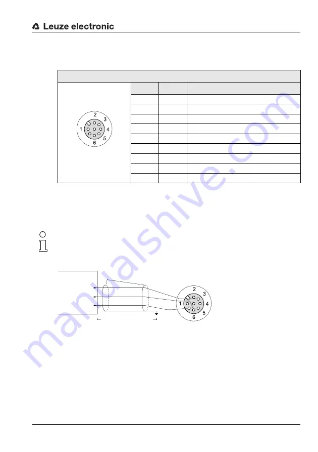
RS 232 cable assignments
Figure 5.5:
RS 232 pin assignments
Switching input / output
The freely configurable switching inputs/outputs are described in chapter 5.2.1.
BUS OUT (8-pin socket, A-coded)
Pin
Name
Remark
1
IO5
Configurable switching input/output 5
2
IO6
Configurable switching input/output 6
3
GND
Negative supply voltage 0VDC
4
IO7
Configurable switching input/output 7
5
IO8
Configurable switching input/output 8
6
Rx
Rx signal (RS 232)
7
Tx
Tx signal (RS 232)
8
FE
Functional earth
Thread
FE
Functional earth (housing)
Table 5.2:
Pin assignment BUS OUT
IO6
IO7
IO5
IO8
Rx
Tx
GND
FE
BUS OUT
7
M12 socket
(A-coded)
IO6
IO7
IO5
IO8
Rx
Tx
GND
FE
BUS OUT
7
Host
GND
Tx
Rx
up to 10m
Shield


