background image

CAUTION 

- All the pneumatic connections must be

tight enough to be leak proof for proper operation. Air
connections MUST be checked with a soapy water
solution and bubble tight.

W A R N I N G  

- Keep stop valves closed until all

adjustments and checks in steps 2 -10 are completed.

W A R N I N G  

- Turn off electrical power before

removing the internal field wiring panel.

2)

Take off field wiring panel by loosening screws.

3)

Set the direct/reverse switch (SW3) to the proper
position. (See Figure 7). When set on direct, the air
output will increase when the signal from the
transmitter increases and vice versa.

For example, if the system is being used to control
pressure downstream of a normally closed control valve,
reverse action would be required (increasing system
pressure will increase the signal from the transmitter
and this must produce a decrease of output signal air
pressure to close the control valve).

4)

Install the set point selector jumper J16-J21. This
jumper allows the PMC-1 to operate in one of two
different set point modes, local or remote.

LOC

Local set point

REM/LOC
REM/LPOS
REM/VENT
REM/LOAD   

}

REM/ZERO    

Installing jumper in ‘LOC” (local) position allows set
point adjustments using the up or down push buttons
located on the front panel, only when the “SP” LED is lit.
By inserting the jumper in any of the remaining five
positions, the controller accepts a (4-20mA) external set

Remote set point
with selection of
defaults.

4.

Terminals 8 through 12 have been reserved for adding
future options to the controller.

5.

Terminals 13, 14, 15 are used to connect the optional
local control module model RCS-90. This module can be
used if the PMC-1 is mounted at a remote location from a
control valve.

6.

When the PMC-1 is being used as a temperature
controller with an RTD, an optional signal conditioning
card, calibrated for a temperature range suitable for the
process, must be installed in TB 5. Jumper at J5/J6 must
be on J6. (See figure 7) For a 3 wire RTD, connect the
two RTD wires that are internally connected together
(zero resistance between them) to terminals 16 and 17
and the remaining connection to terminal 18 of TB-2.
(See Figure 5). For a 2 wire RTD, jump terminals 16 and
17. (See Figure 6). See Appendix C for guidelines on
practical distance limitations.

7.

Power and signal lines should be routed through separate
conduits to avoid interference. Set the 115/230 voltage
switch (SW1) to match the supply voltage. 

DO NOT TURN

ON A.C. POWER YET

. With AC power circuit breaker

OFF, connect power leads (unpowered) to TB-1 (Figure 7).
Connect the black wire (HI) to terminal 1, the white wire
(LO) to terminal 2 and the green or green/yellow earth
ground wire to terminal 3 of TB-1. If the PMC-1 is power-
ed by 24v DC, connect the positive connection to terminal
6 and the negative connection to terminal 7 of TB-2, and
DO NOT connect any wires to TB-1. (See Figure 8).

8.

For 4-20mA output, connect recorder, alarms or other
auxiliary device to TB-7 noting the polarity. NOTE: The
4-20mA output will be within ±0.5% (of span) of the
value indicated on the PMC-1. Re-calibrate the remote
device to agree with the PMC-1, do not re-calibrate the
PMC-1. 

D. Start-Up

1)

Close stop valves upstream and downstream of the
diaphragm control valve.

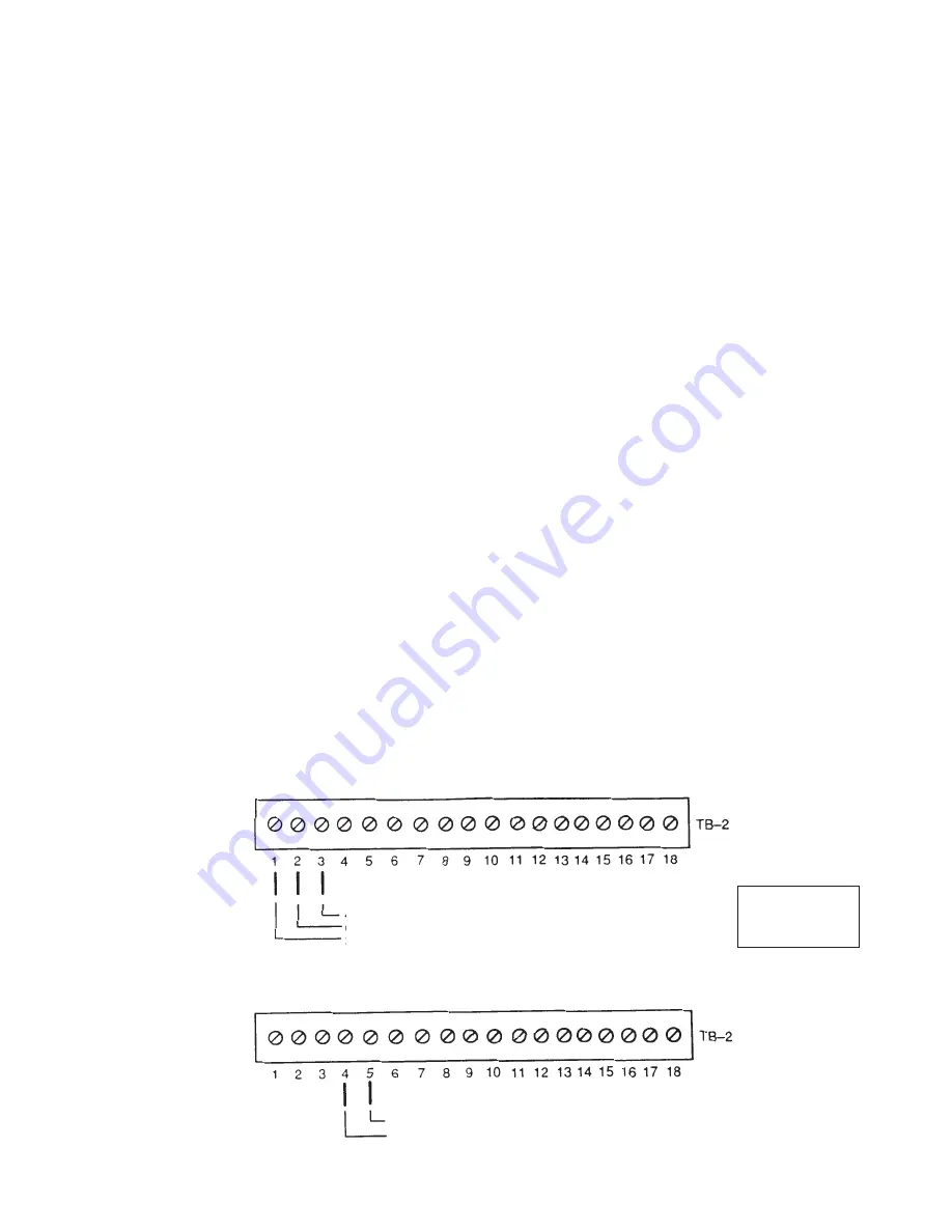
WIRING DIAGRAMS FOR TYPICAL INSTALLATIONS

Wiring Connections for 4—20 mA Transmitter (e.g. pressure or level)

4—20 mA transmitter return
Ground
24 VDC power output to transmitter

Wiring Connections for External Set Point

4—20 mA input
4—20 mA return

FIGURE 3

FIGURE 4

5

NOTE: 

Jumper J5/J6 

must be on J5

Summary of Contents for PMC-1

Page 1: ...AND MAINTENANCE INSTRUCTIONS DIAGRAMS PARTS LIST 12501 Telecom Drive Tampa FL 33637 PMC 1 ELECTRO PNEUMATIC CONTROLLER T A B L E O F C O N T E N T S Specifications 2 Introduction 4 Operation 4 Installation 4 Pneumatic Connections 4 Field Wiring 4 Start Up 5 Troubleshooting 6 ...

Page 2: ...TION NO AIR CONSUMPTION AT STEADY STATE DISPLAY 3 1 2 DIGIT LCD BACKLIT DISPLAY GREEN BACKGROUND ACCURACY 0 5 OF FULL SPAN SETTING ACCURACY ACTUAL SET VALUE COINCIDES WITH INDICATED SET VALUE RESPONSE SPEED RANGE 200 1 AMPLIFIER GAIN SLOW LOOP NORMAL 6 MAX HIGH 12 MAX DEAD BAND ADJUSTABLE FROM 0 TO 5 OF FULL SPAN INPUT RESISTANCE TO CURRENT LOOP 100 OHMS X CURRENT 0 7 VOLTS AMBIENT TEMPERATURE 4 F...

Page 3: ...3 PMC CONTROLLER MOUNTING DIMENSIONS INCHES MM A C Power Electrical Signal Input Output Pneumatic Input 100 psi Max Vent Pneumatic Output FIGURE 1 ...

Page 4: ...current flows into terminal 5 and terminal 4 is negative See Figure 4 A Introduction The Leslie PMC 1 electro pneumatic controller can be used to control pressure temperature liquid level and other process variables It accepts signals from any standard 4 20 mA transmitter and provides a pneumatic output to operate a diaphragm control valve etc It provides the following features 1 The controller su...

Page 5: ...remote location from a control valve 6 When the PMC 1 is being used as a temperature controller with an RTD an optional signal conditioning card calibrated for a temperature range suitable for the process must be installed in TB 5 Jumper at J5 J6 must be on J6 See figure 7 For a 3 wire RTD connect the two RTD wires that are internally connected together zero resistance between them to terminals 16...

Page 6: ...ated to read 25 0 when the CALIBRATE LO LED is lit and 175 0 when the CALIBRATE Hl LED is lit J7 0 000 to 1 999 J8 00 00 to 19 99 J9 000 0 to 199 9 J10 0000 to 1999 10 Using one of the pressure sensitive labels supplied label the display to indicate the unit of measurement for your process i e pressure temperature gpm etc 11 Adjust the air supply pressure to the controller by adjusting the filter ...

Page 7: ...lack Red TB 2 Approximate resistance 0 Ω Approximate resistance 75 F 109 Ω Unused terminal not connected 3 Wire RTD Head Wiring Connections for Two Wire RTD temperature Jump Black RTD lead Red RTD lead Terminal colored red or other contrasting color NOTE Jumper J5 J6 must be on J6 ...

Page 8: ... cable that the shielding is connected to the earth ground 4 Insufficient air pressure to PMC 1 a Make sure that the air pressure supplied to the PMC 1 is sufficient to fully stroke the control valve or to provide the maximum outlet pressure required from a regulator 5 Leaks in pneumatic lines a Small pneumatic line leaks can cause control instability particularly when using the PMC 1 with a regul...

Page 9: ...ED AND EXTERNAL POWER CAN BE BROUGHT TO THE SOLENOIDS AT TB 2 PIN 14 J5 JUMP WHEN EXTERNAL 4 20MA PROCESS FEEDBACK TRANSMITTER IS USED OR J6 JUMP WHEN RTD SIGNAL CONDITONAL CARD IS INDSTALLED IN THE PMC 1 J7 DECIMAL POINT SELECT REFER TO SECTION D PARA 7 J8 DECIMAL POINT SELECT REFER TO SECTION D PARA 7 J9 DECIMAL POINT SELECT REFER TO SECTION D PARA 7 J10 DECIMAL POINT SELECT REFER TO SECTION D P...

Page 10: ... Resistance x Current Voltage 100 x 020 0 7 Voltage 2 7 Volts Thus at 20mA the voltage drop of the PMC s transmitter loop is 2 7 volts EXAMPLE The PMC 1 is being used in a level control application The differential pressure transmitter used to measure the level has a minimum power requirement of 12 volts A chart recorder with an impedance resistance of 450Ω is being considered for use with the lev...

Page 11: ...l 3 receives the 4 20mA signal back 11 Terminal 2 is an earth ground A 4 wire transmitter needs two additional wires because it receives its power from a separate power source This type of transmitter can also be used with the PMC 1 and it is connected as shown in Figure 9 Since it receives its power from a separate source terminal 1 the PMC 1 s power is not used The 4 20mA signal from the transmi...

Page 12: ...alled in the PMC 1 is a variable voltage signal The signal conditioning card converts the voltage signal into a 4 20mA signal which can be used by the PMC 1 The wire connecting the RTD to the PMC 1 provides additional resistance which varies according to the gauge and length of the wire Although the additional resistance of the wire is insignificant over short distances it can affect accuracy over...

Page 13: ... cases the arrangement shown above is recommended A standard three way solenoid valve is installed in the air line between the PMC 1 and the control valve The solenoid is energized from the same power source used by the PMC 1 When the solenoid is energized ports B and C are connected and the pneumatic circuit between the PMC 1 and control valve is complete On loss of power the solenoid is no longe...

Page 14: ...oning card to the set point and using a series of short pneumatic pulses modulates the control valve as required to maintain the set point The PMC 1 s slow loop control mode can be selected for enhanced control in systems that respond slowly to control valve changes During installation the PMC 1 is calibrated by dialing in the upper and lower limits of the signal conditioning card The set point an...

Page 15: ...solating valve The isolating valve provides the ability to change or calibrate the pressure transmitter without otherwise disturbing the system The pig tail is important in steam applications to avoid overheating the pressure transmitter The loop in the pig tail maintains a condensate buffer between the steam and the sensing diaphragm of the pressure transmitter During installation the PMC 1 is ca...

Page 16: ...ine measures the static pressure in the system and acts as a reference point the difference between the upper and lower sensing lines is the head pressure of the liquid In an open system the reference line is vented to atmosphere A three valve manifold is recommended for use with the dp transmitter to facilitate isolation of the transmitter for replacement or in line calibration During installatio...

Reviews: