background image

Electric Power Generation 

Installation and maintenance 

5

8

76 en - 2020.01 / 

a


TALA44 

Low Voltage Alternators - 4 pole 

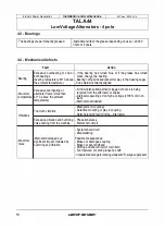
4.3 - Bearings 

The bearings are permanently greased 

Approximate life of the grease (depending on use)= 20,000 

hours or 3 years. 

4.4 - Mechanical defects 

Fault 

Action 

Excessive overheating of one or  - If the bearing has turned blue or if the grease has turned 

Bearing 

bath bearings 

(bearing temperature 80

°

C above 

black, chan�e the bearing.

- Bearing not  ully locked (abnormal play in the bearing cage)

the ambient temperature) 

- End shields incorrectly aligned

Excessive overheating of 

-Air flow (inlet-outlet) partially clogged or hot air is being

recycled from the alternator or engine

Abnormal  alternator frame (more than 

-Alternator operating at too high a voltage (>105% of Un on

temperature  40

° 

C above the ambient 

load) 

temperature) 

-Alternator overloaded
- Misalignment (coupling)

Too much vibration 

- Defective mounting or play in coupling

Vibrations 

- Rotor balancing fault (Engine -Alternator)

Excessive vibration and humming  - Phase imbalance 

noise coming from the machine  - Stator short-circuit

- System short-circuit

- Misparalleling

Abnormal  Alternator damaged by a 

Possible consequences

noise 

significant impact, followed by 

- Broken or damaged coupling

humming and vibration 

- Broken or bent shaft end

- Shifting and short-circuit of main field

- Fan fractured or coming loose on shaft

- lrreparable damage to rotating diodes/AVR, surge suppressor

16 

LEROY-SOMER '" 

Summary of Contents for TAL A44

Page 1: ......

Page 2: ...ur attention to the following 2 safety measures which must be complied with a During operation do not allow anyone to stand in front of the air outlet guards in case anything is ejected from them b Do not allow children younger than 14 to go near the air outlet guards A set of self adhesive stickers depicting the various warning symbols is included with this maintenance manual They should be posit...

Page 3: ...10 3 1 Assembly 10 3 2 Checks prior to first use 11 3 3 Terminal connection diagrams 11 3 4 Commissioning 14 3 5 Setting up 14 4 SERVICING MAINTENANCE 15 4 1 Safety measures 15 4 2 Routine maintenance 15 4 3 Bearings 16 4 4 Mechanical defects 16 4 5 Electrical faults 17 4 6 Dismantling reassembly 19 4 7 Installation maintenance of the PMG 20 4 8 Table of characteristics 21 5 SPARE PARTS 23 5 1 Fir...

Page 4: ...ator quickly and accurately we suggest you fill in its specifications on the nameplate below mJ o liDate r p m 11 HzllWeight F Il îh class 11Altitude A V R Excit 1fu l l loo d V A L__II atnoload A 1D E bearin g 1iN D E bearing CE lEC f 0014 1 5 o 8518 3 NEM A Mtl Jl n 1 4 Storage Prier to commissioning machines should be stored away from humidity 90 after a long period of storage check the machine...

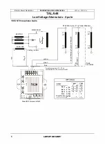
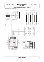
Page 5: ...n Mounting arrangement single bearing with standard feet and SAE flanges coupling dises Drip proof machine self cooled Electrical options Space heaters ln order to conform to standard EN 61000 6 3 EN 61000 6 2 EN 55011 the R791 interference suppression kit is needed SHUNT dedicated single phase4 wire ROUE POLAIRE MAIN FIELD EXCITATRICE EXCITER 5 Induit T1 U1 T3 U5 1 i 1 STATOR Annature Inducteur T...

Page 6: ... 0 SL UF MAIN FIELD E I Rotating rectifiers ConsultR120manual ref 5243 V STATOR 6 wire T1 to T6 identification 0 yellow green blue T1 U1 T4 U2 For delta connection 1PH 3PH 0 use terminais N and U connect N and N1 C 0 Q C C 0 u C Cl C C C Q Q C C 0 u 0 C OPTIONAL R791T Black Black Black Blue Green Yellow LEROY SOMER T2 V1 T5 V2 î C 0 t5 Q L C C Cl C 0 Cl u T3 W1 T6 W2 0 Delta connection ...

Page 7: ...1 Rotating rectifiers blue yellow white green For F and FF connection link N and N1 D T10 T1 l l J C C 01 l 1 0 C 1 1 C Cl 3 PH A T3 T1 N C T2 T2 N C j l 01 1 F T2 T1 N C N C i 1 OPTIONAL w en J LL R791T 3PH y T1 T1 T2 T2 T3 T3 l 00 l 1 ai 1 PH FF T10 T1 N C N C 1 PH L L M t I O O O OPEN FOR 6DHz t b_ ili __ 1 Black Black Black Blue N e 1 SL UF OE UF S V ConsultR120manualref 5243 GreenNellow LEROY...

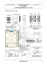
Page 8: ... 044 seul Oj ianeli JICT forTAL D4 I on1y STATOR 6 PT lm qtl ël9 frnan T1 â fu T6 1104arloo T4 3 PH 1 PH A 7 D F FF 1 r T3 T10 T2 T1 Détection sef on ten siQn J 7 tmœ roup1ages A et FF avec 12 is s euterne1 Connectïcn A FF wilh 12 wires o niy Sensing aco ifl ling to voilage 1 1 1 V Vil fur hi gh vclmge 3BD 480V L1fL2 for krlN voilage 190 24DV See dia lram 3 530 or 3534 Nota L __ Pour Sens anti hor...

Page 9: ... 1 1 1 1 __ J 1 1 STATOR 6 i marr iu rnm T1 âiro l ô 1104 fiWIOO T4 3 PH 1 Pl Al il D F FF T3 110 T2 7 1 1 1 1 1 h 1e étwlioOJ sefoa temsfou l seos ng aœordîng to voltage V W for hfgh voilage 3004B V L 1ll2 row wltage 2DB 24D IJ See diagram 3630 or 35 34 coupfages A et FF avec 2 fils seulemer Connecti on A FF lri Jl 12 wires ooty SellSanU horaire For arnti clock wise rofatiofl 8 01 7 02 OPTmN 1111...

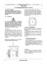
Page 10: ...w anyone to stand under the load c i c i c i c i c i The TAL A44 is equipped with two air deflectors that prevent access to the upper and lower holes of the flange Coupling for this machine should be done with bolts in the eight accessible holes disregarding the ones that cannot be accessed because of the deflectors Îi i z r _ 0 9 p o o o Ô P S 0 Accessibla mgle bearmgcoup11ng Before coupling chec...

Page 11: ...lternator has the degree of protection matching the defined environmentalconditions Mechanical checks Before starting the machine for the first time check that all fixing bolts are tight the length of boit and the tightening torque are correct the cooling air is drawn in freely the protective grills and housing are cor rectly in place the standard direction of rotation is clock wise as seen from t...

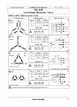
Page 12: ... L U 1 L1 L 5876 en 2020 01 a Connection codes Voltage Detection Factoryconnection 12 3PH L1 U Star T1 T4 T5 TI L3 W L2 V Della T4 1PH or 3PH L3 W 1 1 L2 V L T5 T2 L Winding 6S 8S Lt Winding 6S BS Lh 50Hz 60 Hz 380 415 380 480 380 416 AREP R180 W T3 V T2 50Hz 60Hz 220 240 220 240 OUTPUTS TO THE RIGHT EARTH 1_ W 3 L3 V 2 L2 U 1 L1 TG T5 EARTH 200 220 240 1ph 3ph W J l3 AREP R180 L V 2 L2 L2 T3 1 L1...

Page 13: ... 380 480 8 380 416 SHUNT R120 U T1 V T2 N T10 N1 n c AREP PMG R180 W T3 V T2 Winding 50Hz 60Hz 6 220 240 220 240 8 200 220 240 T6 T5 T4 T9 TB T7 T6 T9 SHUNT R120 M T5 TB U T1 N1 T2 N T3 V n c T4 T7 AREP PMG R180 L2 T3 L1 T2 5876 en 2020 01 a Factor connection DE __ W 3 L3 _ V 2 L2 _ U 1 L1 NOE DE NOE DE W 3 L3 e a V 2 L2 NDE lfcounterclockwise L2and L3inverted 1PH L VoltageLM 1 2voltage LL Winding...

Page 14: ...own in the terminal connection diagram The alternator earth terminal inside the terminal box is connected to the electrical earth circuit The earth terminal is connected to the frame The connections inside the terminal box must never be subjected to stress due to cables connected by the user 3 4 Commissioning Lt The machine can only be started up and used if the installation is in accordance with ...

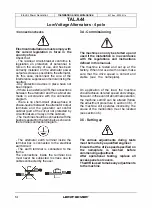
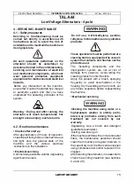
Page 15: ...rical connections in the installation Electrical servicing Commercially available volatile degreasing agents can be used WARNING Do not use trichlorethylene perchlo rethylene trichloroethane or any alkaline products These operations must be performed at a cleaning station equipped witha vacuum system that collects and flushes out the productsused The insulating components and the impregnation syst...

Page 16: ...ogged or hot air is being recycled from the alternator or engine Abnormal alternator frame more than Alternator operating at too high a voltage 105 of Un on temperature 40 C above the ambient load temperature Alternator overloaded Misalignment coupling Too much vibration Defective mounting or play in coupling Vibrations Rotor balancing fault Engine Alternator Excessive vibration and humming Phase ...

Page 17: ...Speed tao low lncrease the drive speed do not touch theAVR voltage pot before running at the correct speed Voltage AdjustAVR volt Adjustment ineffective FaultyAVR tao high age potentiometer Voltage Check the speed possibility of cyclic irregularity oscilla AdjustAVR stabil Loose connections tians ity potentiometer FaultyAVR Speed tao low when on load Voltage Voltage between F1 and F2 DC Check the ...

Page 18: ...arate excitation Assembly A Connect a 12 V battery in series with a rheostat of approximately 50 ohms 300W anda diode on bath exciter field wires 5 and 6 ASSEMBLY A 6 _ Field 5 Rh 50 300W Assembly B Connect a Variac variable power supply and a diode bridge on bath exciter field wires 5 and 6 Bath these systems should have characteristics which are compatible with the field excitation power of the ...

Page 19: ...torque See section 5 4 Access to diodes Remove the airintake grille 51 Checkall 3 modules using an ohmmeter or a battery lamp Refit the modules Refit the air intake grille 51 Access to connections and the regulation system The terminais are accessed directly by removing the terminal box lid 48 Replacingthe NDE bearing on single bearing machines Dismantling Remove the terminal box lid 48 Unscrew th...

Page 20: ... Rest the rotor on one of its pales then siide it out Use the tube as a lever arm to assist dismantling After extraction of the rotor be careful not to damage the fan or dismantle it Remove the revolving field coil rotor and place on special V shaped supports NOTE If intervention is required on the revolving field coil rewinding replacement of components the rotor assembly must be rebalanced Reass...

Page 21: ...ated loadwith separate field excitation Ali values are given at 10 for exact values consult the test report and are subject to change without priorwarning Dedicated single phase M 4 pole SHUNT excitation 4 wire Resistances at 20 c 0 Series connection Type UN stator Rotor Field coil Armature C 0 024 2 35 11 65 0 423 D1 0 019 2 64 12 94 0 459 J 0 014 3 15 12 94 0 459 Resistances at 20 C 0 Series con...

Page 22: ...iliary Z1 Z2 auxiliary windings windings A 0 450 0 657 B 0 450 0 657 C 0 436 0 627 D 0 436 0 627 E 0 365 0 575 H 0 365 0 575 J 0 308 0 480 K 0 417 0 611 Table of weights values given for information only Three phase SHUNT AREP 6 and 12 wire Type Totalweight kg Rotor kg A 262 108 B 262 108 C 295 121 D 295 121 E 368 154 H 368 154 J 398 166 K 433 181 Dedicated single phase M SHUNT 4 wire Type LIN sta...

Page 23: ...umber and the information given on the nameplate Address your enquiry to your usual contact Part numbers should be identified from the exploded views and their description from the parts list Our extensive network of service centres can dispatch the necessary parts without delay To ensure correct operation and the safety of our machines we recommend the use of original manufacturer spare parts ln ...

Page 24: ...tric Power Generation I Installation and maintenance 1 TALA44 Low VoltageAlternators 4 pole 5876 en 2020 01 a 5 4 Exploded view parts list and tightening torque Single bearing SHUNT orAREP Çl 24 LEROY SOMER ...

Page 25: ... 1 Earth continuity bolts M6 10 124 1 Terminal block M6 5 30 1 Drive end DE shield 144 1 Terminal box 31 8 Fixing bolts M12 69 198 1 Voltage regulator MS 3 6 AVR 1nterference 32 1 S A E adaptor ring 199 1 suppression module MS 6 RFI kit 33 2 Protective guard M6 5 320 1 Coupling sleeve 36 1 Non drive end NOE 322 2 Coupling dises shield 37 4 Tie rod M14 90 323 8 Fixing bolts M16 320 40 2 Plastic cov...

Page 26: ...esses Our technical support depar tment can provide detailed directions on products dismounting upon request Waste hazardous materials The following components and materials need a special treatment and need to be separated from the alternator before the recycling process electronic materials found in the terminal box including the Automatic Voltage Regulator 198 Current Transformers 176 interfere...

Page 27: ......

Page 28: ...Linkedin com company leroy somer Twitter com EPG_Alternators Facebook com LeroySomer EPG YouTube com LeroySomerOfficiel _ _ Il for dreams TM LEROY SOMER www leroy somer com epg 5876 en 2020 01 a ...

Reviews: