21
Installation and maintenance
LSRPM - PLSRPM
Synchronous permanent magnet motors
LEROY-SOMER
4155 en - 2012.05 / e
6 - CORRECTIVE MAINTENANCE:
GENERAL
- open the terminal box, mark the wires and their positions,
- disconnect the power supply wires,
- uncouple the motor from the equipment being driven.
Always use an extractor to remove any devices mounted on
the motor shaft extension.
6.1 - Dismantling the motor
Refer to the detailed instructions for the relevant motor range
(see following pages).
It is advisable to mark the shields in relation to the stator and
the direction in which the fan is mounted on the rotor.
6.2 - Checks before reassembly
Stator :
- remove any dust from the stator:
if the winding needs to be cleaned, a suitable liquid must be
used: dielectric and inert on the insulating components and the
external finish.
- check the insulation (see section 2.1) and if necessary, dry it
in an oven.
- clean the spigots thoroughly, and remove all traces of impact
on the mating surfaces if necessary.
Rotor:
- clean and check the bearing running surfaces. If they are
damaged, renew the running surfaces or change the rotor.
- check the condition of the threads, keys and their housings.
End shields:
- clean off any traces of dirt (old grease, accumulated dust,
etc).
- clean the bearing housings and the spigot.
- if necessary, apply anti-flash varnish inside the end shields.
- carefully clean the bearing retainers and the grease valves (if
these are fitted on the motor).
6.3 - Mounting the bearings on the shaft
This operation is extremely important, as the slightest
indentation of a ball on the bearing tracks would cause noise
and vibration.
Lightly lubricate the running surfaces of the shaft.
There are a number of ways of mounting the bearings correctly:
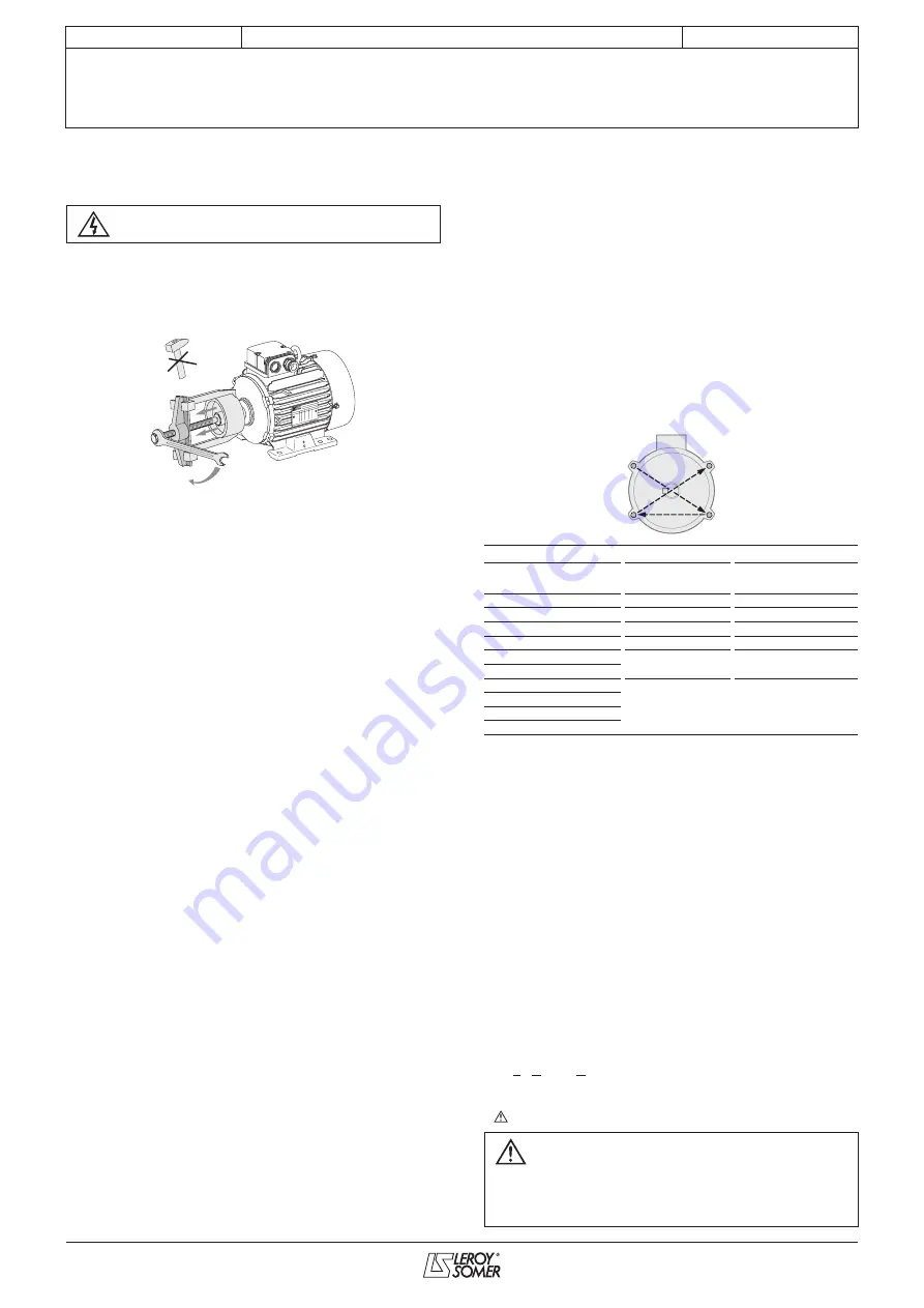
- cold state: The bearings must be mounted without any impact,
using a spanner (do not use a hammer). The force applied must
not be transferred to the bearing track. You should therefore
use the internal cage for support (taking care not to press on the
seal shield for sealed bearings).
- hot state: Heat the bearing to between 80 and 100°C: in a
dryer, an oven or on a heating plate.
(A blowtorch or an oil bath must never be used).
After dismantling and reassembling a bearing, all the spaces
between the seals and labyrinth seals must be filled with
grease in order to prevent the entry of dust and the rusting of
machined parts.
See detailed instructions for the relevant motor ranges in the
following pages.
6.4 - Reassembling the motor
Care must be taken to ensure that the stator is replaced in
its original position,
so that the stack of laminations is centred
correctly (generally with the terminal box facing forward) and
the water drain holes are positioned correctly if they are on the
housing.
Tightening the tie rods
These must be tightened diagonally, to the torque indicated
(see below).
Tie rod tightening torque
Type
Rod/screw Ø
Tightening torque
N. m ± 5 %
90
M5
4
100
M5 ou M6
4
132
M7
10
160
M8
18
200
M10
25
225 ST/MR
225 MG
M12
44
250
280
315
6.5 - Reassembling the terminal box
Reconnect all the power supply wires in accordance with the
diagram or markings made before dismantling.
To ensure the box is properly sealed: check that the cable
glands on the box and the cable(s) have been retightened, and
ensure that the seal has been correctly positioned before
closing. For terminal boxes equipped with a horn (part no. 89
on the exploded views) or/and a cable gland support plate,
ensure that the seal has been correctly positioned before
closing. Check that the terminal box components are tightened
correctly.
Note: It is advisable to test the motor at no load
- If necessary, repaint the motor.
- Mount the transmission device on the motor shaft extension
and reinstall the motor on the machine to be driven.
6.6 - Checking the Hall effect sensors
- Rotate the motor (if necessary uncouple).
- Using a voltmeter, check that the voltages between the 0 V
and U, V and W and U, V, W change correctly from 0 V to
approximately 13.5 V when the shaft rotates.
- Contact between wires
First switch off and lock the power supply.
1
4
3
2
For any given position of the motor shaft, the
voltages on the 3 phases must not be
simultaneously either 0 V or 13.5 V.
For replacement of the sensors, refer to the section on
dismantling/reassembly.


