9
Commissioning
DYNEO
®
Synchronous motors with permanent magnets-drive
4474 en - 2011.04 / e
LEROY-SOMER
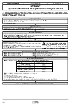
•
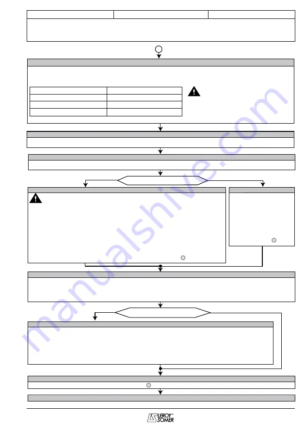
3.34
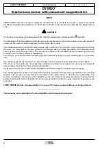
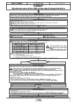
: Drive encoder lines per revolution
•
3.36
: Encoder supply voltage
•
3.38
: Type = AB servo
• Clear the “Enc x” trip with a reset if necessary
Enter the characteristics of the incremental encoder
•
0.03
: Acceleration rate = 3
•
0.04
: Deceleration rate = 5
•
6.01
: Type of stop = rp
•
6.08
: Standstill torque = 0
Preset the control parameters
Possible to uncouple the motor?
YES
NO
The drive is ready to operate, or waiting for additional parameter settings
Brake present?
YES
NO
•
X.00
: Enter the value 1000, then press the Reset key
Storing
•
12.41
: Enable brake control
1(rel): The drive relay (terminals 41, 42) is assigned to the brake released item (
12.40
). The "drive ready" item is
then redirected towards logic output terminal 25.
2 (dIO): The logic output terminal 25 is assigned to the brake released item (
12.40
).
3(User): Free assignment of the brake released item (
12.40
).
For value 3(User) and to refine the additional brake control settings (time delays, current levels, etc), see menu 12
of section H3.21 of manual ref. 3616 and the "Parameter explanations" manual, ref. 3655.
Setting the control parameters for the motor brake managed by the drive
Manual parameter setting
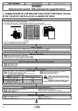
• Check that the motor is stopped and has been uncoupled from the load.
• If a brake is present, check that it has been released (reactivate the brake after
autotuning).
• Check that there is no danger to personnel and equipment.
• Once the procedure is complete, the motor stops automatically.
• The procedure can be interrupted at any time by sending a stop command, pressing
the stop button on the keypad or opening the disable circuit.
• Regardless of the required reference and direction of rotation, the motor runs at very
low speed.
• Uncouple the motor.
• Enable the drive (close terminal 31).
• Start autotuning with
0.40
= 2 and a run command
• Check any changes in the value of
3.25
,
4.13
,
4.14
,
5.17
,
5.24
.
• Disable the drive and store with
X.00
= 1000, then press the Reset key
Autotuning with rotation
Optimising performance
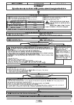
• Couple the load.
• Enable the drive (close terminal 31).
• Start up the machine and re-enter ramps
0.03
,
0.04
and the gains if necessary:
- of the speed controller via
3.10
,
3.11
,
3.42
- of the current loop via
4.13
and
4.14
A
Using the information on the
motor nameplate, set the
following parameters:
•
3.25
: Encoder phase angle
•
5.17
: Stator resistance
•
5.24
: Transient inductance
Start calculating
4.13
and
4.14
via
0.40
= 6 (takes 1s).
• Store with X.00 = 1000, then
press the Reset key .
•
0.02
: Max. speed < 140% of the motor rated speed
5.08
.
•
0.06
: Symmetrical current limiting = 150%.
•
0.41
: The SWITCHING FREQUENCY value must be set
according to the following table:
•
0.42
: Number of poles (calculation: p = 120f / n).
•
0.45
: Motor thermal constant = 89.
•
5.22
: Enable high speed = ON.
Enter the other motor parameters
•
5.35
: Disabling of the automatic switching frequency adjustment = On (1).
•
Before setting the maximum speed,
check that the motor and the machine
can withstand it.
• Respect the supply voltage “Inverter
supply” indicated on the motor nameplate.
5.08
(Motor rated speed)
0.41
(Switching frequency)
N.rated
≤
1800 rpm
1800 rpm < N.rated
≤
3600 rpm
3600 rpm < N.rated
3 kHz
4 kHz
6 kHz


