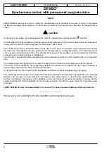
Commissioning
DYNEO
®
Synchronous motors with permanent magnets-drive
6
4474 en - 2011.04 / e
LEROY-SOMER
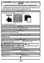
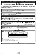
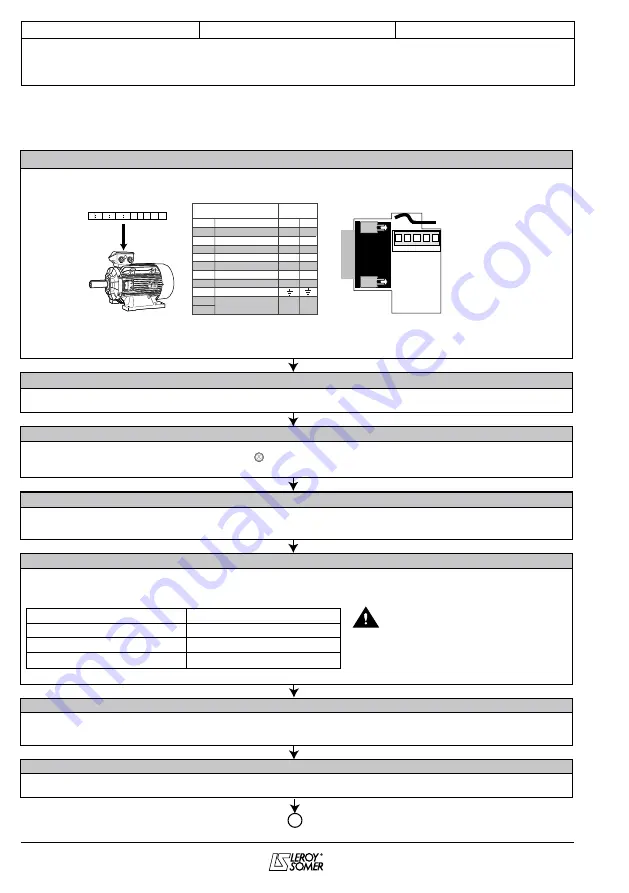
2 - COMMISSIONING OF LSRPM MAGNETS MOTOR WITH FEEDBACK VIA HALL
EFFECT SENSOR, CONTROLLED BY A UNIDRIVE SP DRIVE
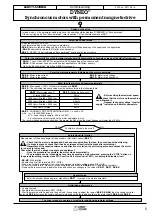
• The order of the motor phases is respected.
• The wiring from the sensor to UT02 conforms to section L11 of manual 3616.
• The drive is disabled (terminal 31 not supplied).
• The run command has not been enabled.
(*) Connect to terminals 8 and 11 of the drive
terminal block
Drive off, check that …
•
0.00
: Enter 1253 in European configuration.
•
0.48
: Select SerVO mode then press the Reset key .
(If a drive trip “Enc x” occurs, continue with the procedure).
Select the control mode
• The drive status is “Inh” or “Enc x” depending on how the speed feedback is configured
• If the drive trips, apart from “Enc x”, refer to section K of the Unidrive SP manual 3616.
Switch on the drive
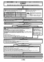
•
0.44
: Motor rated voltage.
•
0.46
: Motor rated current.
•
5.08
: Motor rated speed.
Enter the motor parameters indicated on the motor nameplate
•
0.02
: Max. speed < 140%
of the motor rated speed
5.08
.
•
0.06
: Symmetrical current limiting = 150%.
•
0.41
: The SWITCHING FREQUENCY value must be set
according to the following table:
•
0.42
: Number of poles (calculation: p = 120f / n).
•
0.45
: Motor thermal constant = 89.
•
5.22
: Enable high speed = ON.
Enter the other motor parameters
•
0.03
: Acceleration rate = 3.
•
0.04
: Deceleration rate = 5.
•
6.01
: Type of stop = rp.
•
6.08
: Standstill torque = 0.
Preset the control parameters
•
3.34
: Drive encoder lines per revolution = 0.
•
3.36
: Supply voltage = 15V.
•
3.38
: Type = AB servo.
•
3.39
: Impedance matching = 0.
• Clear the “Enc x” trip with a reset if necessary.
Enter the characteristics of the Hall effect sensor
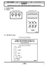
LSRPM
1 2 3 4 5 6
7
8 9 10 11
1
2
3
4
5
6
7
8
9
10
11
15V
OUT 0V A/U
0V
2
1
3 4 5
A
U
W\
V
U\
W
V\
0V
+15V
Shielding
Motor thermal
sensor (*)
11-pin terminal block on Hall
effect sensor end
UT02 terminal
block
U
x
V
x
W
x
0V
+15V
3
x
4
x
5
x
2
1
• The connections have been made as indicated below, depending on which motor is used.
UT02
x
x
5.08
(Motor rated speed)
0.41
(Switching frequency)
N.rated
≤
1800 rpm
1800 rpm < N.rated
≤
3600 rpm
3600 rpm < N.rated
3 kHz
4 kHz
6 kHz
•
5.35
: Disabling of the automatic switching frequency adjustment = On (1).
• Before setting the maximum speed,
check that the motor and the machine
can withstand it.
• Respect
the supply voltage “Inverter
supply” indicated on the motor nameplate.


