background image

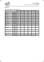
Rated data

Inverter power supply 400 V, self-ventilated motors

Motor


M85AS120S40 M85AS120M4

0

M85AS120L40 M85AS140S32 M85AS140M3

2

M85AS140L32

Standstill torque

M

0

Nm

6.50

11.0

15.0

11.0

21.0

28.0

Rated torque

M

rated

Nm

4.80

7.40

9.00

8.50

14.0

17.4

Max. torque

M

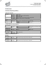
max

Nm

14.5

29.0

44.0

26.0

53.5

80.0

Rated speed

n

rated

rpm

3960

3960

3960

3240

3240

3240

Max. speed

n

max

rpm

6000

6000

6000

6000

6000

6000

Rated power

P

rated

kW

2

3.1

3.7

2.9

4.8

5.9

Standstill current

I

0

A

5.50

8.80

12.1

7.40

14.0

18.0

Rated current

I

rated

A

4.30

6.40

7.80

6.30

10.0

12.2

Max. current

I

max

A

15.0

28.0

42.0

23.0

45.5

66.0

Rated voltage

V

rated

V

330

330

320

340

330

330

Rated frequency

f

rated

Hz

330

330

330

270

270

270

Moment of inertia

J

kgcm²

6.50

12.4

18.2

15.7

30.1

44.6

Efficiency

η


0.902

0.914

0.914

0.879

0.915

0.926

Torque constant

Kt

0 150

°C

Nm/A

1.18

1.25

1.24

1.49

1.50

1.56

Voltage constant

KE

LL 150

°C

V/
(1000/
min)

68.99

73.1

72.93

86.81

88.36

90.67

Stator terminal resistance

R

UV 20

°C

Ω

2.24

1.02

0.63

1.436

0.562

0.366

Stator terminal resistance

R

UV 150

°C

Ω

3.376

1.537

0.949

2.164

0.847

0.552

Stator inductance

L

mH

11.5

6.73

4.58

9.90

5.22

3.76

Weight

m

kg

6.5

9.25

12.0

9.50

14.5

19.5

Technical data

Rated data

Inverter power supply 400 V, self-ventilated motors

33

Summary of Contents for m850

Page 1: ...Servo motors m850 synchronous servo motor Mounting and switch on instructions EN...

Page 2: ......

Page 3: ...Installation 18 Dimensions 18 Mounting 19 Electrical installation 20 Important notes 20 Preparation 20 Motor connection 21 Connection via ICN connector 21 Commissioning 27 Important notes 27 Before i...

Page 4: ...her with the complete documentation of the product For safety rated attachments observe the enclosed operating instructions of the manufacturer The document includes safety instructions which must be...

Page 5: ...er documentation with additional information Example EDKxxx see documentation EDKxxx Layout of the safety instructions DANGER Indicates an extremely hazardous situation Failure to comply with this ins...

Page 6: ...personal injury and damage to property Observe all specifications of the corresponding documentation supplied This is the precondition for safe and trouble free operation and for obtaining the product...

Page 7: ...cts comply with the applicable national accident prevention regulations The electrical installation work must be carried out according to the appropriate regulations e g cable cross sections fusing PE...

Page 8: ...Directive 2014 30 EU The product is not a household appliance Instead it is a component that is intended exclusively for further use in the context of commercial or professional use as defined by EN...

Page 9: ...ns The product does not provide any safety related functions A higher level safety system must be implemented Provide additional monitoring and protective equipment complying with the safety regulatio...

Page 10: ...ds of operation with I Irated especially if there is a danger of blocking The integrated overload protection does not prevent overloading under all conditions The fuses are no motor protection Use a c...

Page 11: ...uous standstill torque 5 11 Induced voltage Vin V 8 Brake data 8 2 Brake supply voltage 8 3 Electrical power input 8 4 Braking torque 10 Production data 10 2 Material number 10 3 Serial number 11 Bar...

Page 12: ...Motor protection For the thermal sensors 1x PT1000 2x PTC the short designation PT1k 2PTC is given on the nameplate Product information Identification of the products Nameplates 12...

Page 13: ...190 Motor length Short S Medium M Long L Speed 25 x 100 rpm 25 30 x 100 rpm 30 32 x 100 rpm 32 40 x 100 rpm 40 Degree of protection IP5x 5 IP6x 6 Cooling No cooling S Brake attachment No brake 0 Spri...

Page 14: ...phase AC motors 1 Number of pole pairs for resolvers 2 3 4 Number of bits steps or increments per revolution 20 32 128 512 1024 2048 Supply voltage 5 V 8 V 15 V 24 V Interface or signal level Standar...

Page 15: ...an overview of the elements and connections on the product Their position size and appearance may vary Output flange Output shaft Spring applied brake Motor connection Cooling Feedback Temperature mon...

Page 16: ...olts or support plates Do not damage any components during transport Avoid electrostatic discharges on electronic components and contacts Avoid impacts Check the carrying capacity of the hoists and lo...

Page 17: ...sible in the manufacturer s packaging In dry low vibration environment without aggressive atmosphere Protect against dust and impacts Observe the climatic conditions according to the technical data 4E...

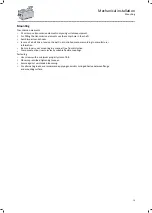
Page 18: ...o avoid tensions Mount belt pulleys sprockets or gear wheels as close as possible to the shaft shoulder in order to keep the bending load of the shaft and the bearing forces at a minimum level Tighten...

Page 19: ...led manner according to manufacturer information Be sure to carry out mounting in a manner free from distortion Compensate minor inaccuracies by suitable flexible couplings Fastening Use screws with a...

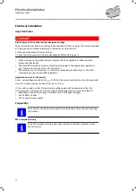
Page 20: ...e system or machine is responsible for adherence to the limits required in connection with EMC legislation Operation on an external inverter A max pulse voltage amplitude of Upk 1560 V at the motor te...

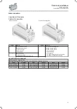
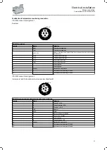
Page 21: ...e value encoder Connection of temperature monitoring 2 ICN M23 connector Feedback connection Connection of temperature monitoring Motor ICN connector assignment Standard connection Power and brake One...

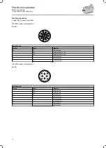
Page 22: ...C 2 BD2 Holding brake DC AC 4 U Power phase U 5 V Power phase V 6 W Power phase W ICN M40 connector assignment 8 pole 1 2 W U V ICN M40 8 pole Contact Name Meaning BD1 Holding brake BD2 Holding brake...

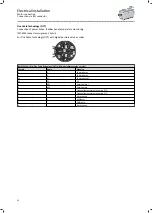
Page 23: ...ed 10 Schirm Encoder housing shield 11 Temperature monitoring PT1000 12 Temperature monitoring PT1000 ICN M23 connector assignment Incremental and SinCos absolute value encoder Hiperface 1 2 3 4 5 6 7...

Page 24: ...V ICN M23 Hybrid for One Cable Technology OCT with digital absolute value encoder Contact Name Meaning U U Power phase U V V Power phase V W W Power phase W PE PE PE A BD1 Holding brake B BD2 Holding...

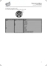
Page 25: ...th digital absolute value encoder Contact Name Meaning U U Power phase U V V Power phase V W W Power phase W A BD1 Holding brake B BD2 Holding brake PE PE PE N Not assigned DSL1 VCC data DSL2 GND data...

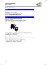
Page 26: ...n connecting the connector to the motor connector make sure that the aids to orientation pos 1 are facing each other 2 Tighten the box nut of the connector Motors with additional PE conductor connecti...

Page 27: ...ence of the motor connection correct Is the contact of good electrical conductivity if a PE connection on the motor housing is used After a long period of downtime or after overhauling the motor check...

Page 28: ...e motors against the ingress of foreign bodies Clean surfaces regularly If equipped with blower clean the air inlets regularly Brake The brakes are not accessible from the outside Maintenance work of...

Page 29: ...operation of the drive system First check the possible causes of malfunction according to the 4Diagnostics and fault elimination 30 If the fault cannot be remedied using one of the measures listed pl...

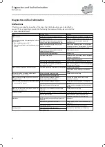
Page 30: ...ing flange during project planning Motor suddenly stops and does not restart Overload monitoring of the inverter is activated Check inverter settings Reduce load caused by longer acceleration times In...

Page 31: ...A 22 2 No 274 UL 1004 6 Protection of persons and device protection Degree of protection EN EN 60529 EN 60034 5 IP54 Information applies to the mounted and ready for use state IP65 Temperature class I...

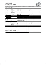
Page 32: ...rating 1000 2000 m amsl Reduce rated output current by 5 1000 m Air humidity Without condensation Average relative humidity 85 Vibration resistance Operation EN IEC 60721 3 3 1995 A2 1997 3M5 only in...

Page 33: ...6 40 7 80 6 30 10 0 12 2 Max current Imax A 15 0 28 0 42 0 23 0 45 5 66 0 Rated voltage Vrated V 330 330 320 340 330 330 Rated frequency frated Hz 330 330 330 270 270 270 Moment of inertia J kgcm 6 5...

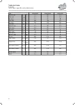
Page 34: ...Max current Imax A 64 0 87 0 112 Rated voltage Vrated V 340 330 345 Rated frequency frated Hz 250 250 210 Moment of inertia J kgcm 60 8 117 193 Efficiency 0 905 0 919 0 929 Torque constant Kt0 150 C...

Page 35: ...ded exposure of substances to humans animals and the environment is excluded Lenze products are industrial electrical and electronic products and are disposed of professionally Both the mechanical and...

Page 36: ...Lenze SE Postfach 101352 31763 Hameln Hans Lenze Stra e 1 31855 Aerzen GERMANY Hannover HRB 204803 Phone 49 5154 82 0 Fax 49 5154 82 2800 sales de lenze com www Lenze com 05 2021 4 0 www Lenze com...

Reviews: