reconnecting them to the storage interposer after removing the backplane or installing a new one.
Other cables might also need to be removed from their retaining clips or moved to the side to
remove the backplane.
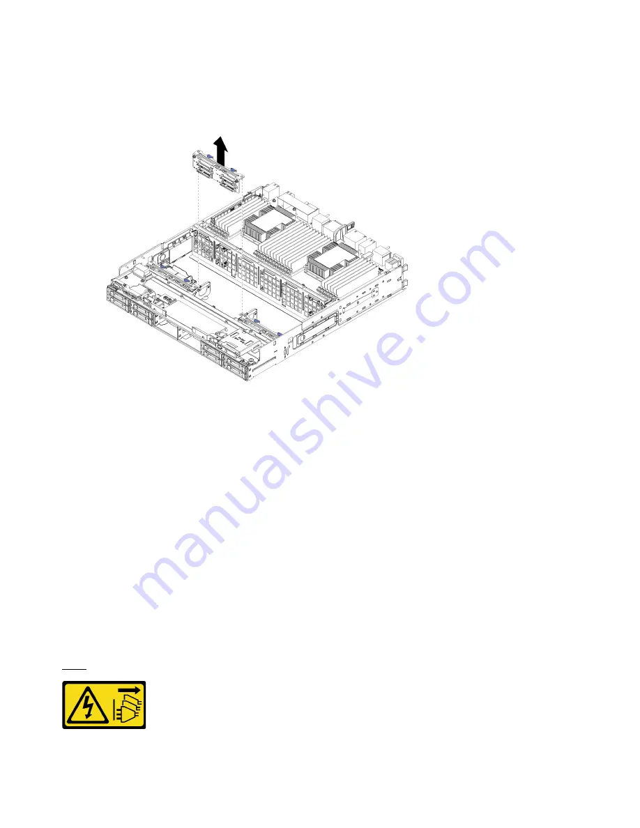
Step 2. Remove the hard disk drive backplane.
Figure 94. Hard disk drive backplane (lower) removal
Grasp the backplane and pull it up and out of the lower tray.
If you are not installing another hard disk drive backplane, after you remove the hard disk drive backplane:
• Replace or reposition the storage interposer. See “Install a storage interposer (lower tray)” on page 373.
• Make sure that all cables are routed and connected.
• Install the fan cage. See “Install a fan cage (lower tray)” on page 320.
• Install the lower compute tray. See “Install a compute tray” on page 307.
• Install the front cover. See “Install the front cover” on page 322.
If you are instructed to return the backplane, follow all packaging instructions and use any packaging
materials that are provided.
Install a hard disk drive backplane (upper tray)
Hard disk drive backplanes in the upper compute tray or optional storage tray are accessed from the front of
the server. There are several types of hard disk drive backplane. Steps that are backplane specific are noted
in each procedure.
S002
CAUTION:
330
ThinkSystem SR950 Setup Guide
Summary of Contents for ThinkSystem SR950
Page 1: ...ThinkSystem SR950 Setup Guide Machine Types 7X12 7X11 and 7X13 ...
Page 55: ...Figure 22 Server components Chapter 2 Server components 51 ...
Page 276: ...272 ThinkSystem SR950 Setup Guide ...
Page 282: ...278 ThinkSystem SR950 Setup Guide ...
Page 286: ...282 ThinkSystem SR950 Setup Guide ...
Page 389: ......
Page 390: ......


