7.
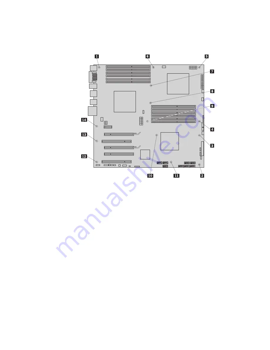
Note the location of all cable connections on the system board and disconnect
all cables. See “Locating parts on the system board” on page 137.
8.
Remove the nine screws that secure the system board to the chassis, following
the sequence shown in the figure:
9.
Carefully lift the system board out of the chassis.
10.
Remove the microprocessor socket cover from the new system board.
11.
Remove the microprocessor from the failing system board and install it on the
new system board. See “Replacing the microprocessor” on page 111.
12.
The failing system board must be returned with a microprocessor socket cover
to protect the pins during shipping and handling. Install the microprocessor
socket cover removed from the new system board on the failing system board.
Note:
The microprocessor socket cover installation procedure should be
performed on both processors.
To install the microprocessor socket cover:
a.
Release the lever securing the microprocessor retainer and open the
retainer to access the microprocessor.
b.
Grasp the microprocessor on the sides and lift it straight up and out of the
socket. Do not touch the contacts on the microprocessor socket.
c.
Align the notches
1
of the microprocessor socket cover with the
alignment keys
2
of the microprocessor socket. Lower the socket cover
straight down into the microprocessor socket on the system board.
152
Hardware Maintenance Manual
Summary of Contents for ThinkStation S20
Page 1: ......
Page 2: ......
Page 3: ...ThinkStation Hardware Maintenance Manual ...
Page 17: ...Chapter 2 Safety information 11 ...
Page 18: ...12 Hardware Maintenance Manual ...
Page 19: ... 18 kg 37 lbs 32 kg 70 5 lbs 55 kg 121 2 lbs 1 2 Chapter 2 Safety information 13 ...
Page 23: ...Chapter 2 Safety information 17 ...
Page 24: ...1 2 18 Hardware Maintenance Manual ...
Page 25: ...Chapter 2 Safety information 19 ...
Page 26: ...1 2 20 Hardware Maintenance Manual ...
Page 33: ...Chapter 2 Safety information 27 ...
Page 34: ...28 Hardware Maintenance Manual ...
Page 35: ...1 2 Chapter 2 Safety information 29 ...
Page 39: ...Chapter 2 Safety information 33 ...
Page 40: ...1 2 34 Hardware Maintenance Manual ...
Page 44: ...38 Hardware Maintenance Manual ...
Page 48: ...42 Hardware Maintenance Manual ...
Page 56: ...50 Hardware Maintenance Manual ...
Page 66: ...60 Hardware Maintenance Manual ...
Page 70: ...64 Hardware Maintenance Manual ...
Page 107: ...Chapter 10 Replacing FRUs Menorca Computers 101 ...
Page 112: ...106 Hardware Maintenance Manual ...
Page 114: ...108 Hardware Maintenance Manual ...
Page 118: ...112 Hardware Maintenance Manual ...
Page 152: ...146 Hardware Maintenance Manual ...
Page 174: ...168 Hardware Maintenance Manual ...
Page 256: ...250 Hardware Maintenance Manual ...
Page 263: ......
Page 264: ...Part Number 53Y4348 Printed in USA 1P P N 53Y4348 ...


