


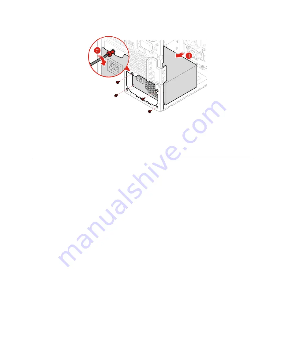
Figure 101. Installing the power supply assembly
7. Connect the new power supply assembly cable to the system board.
8. Reinstall the removed parts. To complete the replacement, see “Completing the parts replacement” on
Replacing the microprocessor
Attention:
Do not open your computer or attempt any repairs before reading the
Important Product
Information Guide
.
CAUTION:
The heat sink and microprocessor might be very hot. Before you open the computer cover, turn off the
computer and wait several minutes until the computer is cool.
1. Remove the computer cover. See “Removing the computer cover” on page 17.
2. Remove the front bezel. See “Replacing the front bezel” on page 18.
3. Pivot the drive bay assembly outward. See “Pivoting the drive bay assembly upward and downward” on
4. Remove the heat sink and fan assembly. See “Replacing the heat sink and fan assembly” on page 58.
5. Disconnect all cables connected to the system board.
6. Replace the microprocessor.
Notes:
• Your microprocessor and socket might look different from the one illustrated.
• Touch only the edges of the microprocessor. Do not touch the gold contacts on the bottom.
• Do not drop anything onto the microprocessor socket while it is exposed. The socket pins must be
kept as clean as possible.
.
61
Summary of Contents for ThinkCentre M920s
Page 4: ...ii M920t User Guide and Hardware Maintenance Manual ...
Page 74: ...70 M920t User Guide and Hardware Maintenance Manual ...
Page 76: ...72 M920t User Guide and Hardware Maintenance Manual ...
Page 78: ...74 M920t User Guide and Hardware Maintenance Manual ...
Page 79: ......
Page 80: ......