
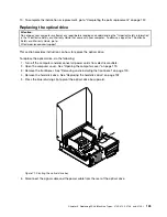


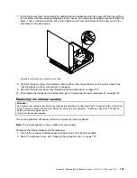

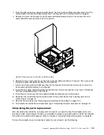

8. Make sure that the new power supply assembly is the correct replacement.
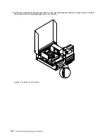
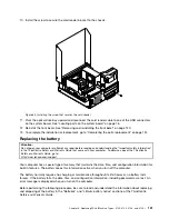
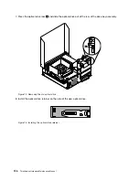
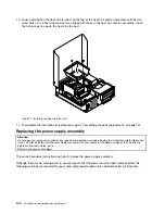
9. Install the new power supply assembly into the chassis so that the screw holes in the new power supply
assembly are aligned with the corresponding holes in the rear of the chassis. Then, install the three
screws to secure the new power supply assembly in place.
Note:
Use only screws provided by Lenovo.
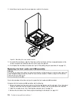
Figure 81. Installing the power supply assembly
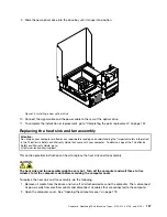
10. Connect the new power supply assembly cables to all drives and the system board. See “Locating
parts on the system board” on page 76.
144
ThinkCentre Hardware Maintenance Manual
Summary of Contents for ThinkCentre M76
Page 6: ...2 ThinkCentre Hardware Maintenance Manual ...
Page 13: ...Chapter 2 Safety information 9 ...
Page 14: ... 18 kg 37 lb 32 kg 70 5 lb 55 kg 121 2 lb 10 ThinkCentre Hardware Maintenance Manual ...
Page 18: ...14 ThinkCentre Hardware Maintenance Manual ...
Page 19: ...1 2 Chapter 2 Safety information 15 ...
Page 20: ...1 2 16 ThinkCentre Hardware Maintenance Manual ...
Page 26: ...22 ThinkCentre Hardware Maintenance Manual ...
Page 27: ...1 2 Chapter 2 Safety information 23 ...
Page 31: ...Chapter 2 Safety information 27 ...
Page 32: ...1 2 28 ThinkCentre Hardware Maintenance Manual ...
Page 36: ...32 ThinkCentre Hardware Maintenance Manual ...
Page 40: ...36 ThinkCentre Hardware Maintenance Manual ...
Page 74: ...70 ThinkCentre Hardware Maintenance Manual ...
Page 116: ...112 ThinkCentre Hardware Maintenance Manual ...
Page 208: ...204 ThinkCentre Hardware Maintenance Manual ...
Page 213: ......
Page 214: ...Part Number 0A94225 Printed in USA 1P P N 0A94225 0A94225 ...