
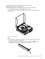
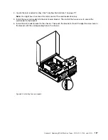


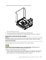


7. Install the screw to secure the card reader bracket to the chassis.
Figure 61. Installing the screw that secures the card reader
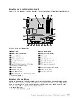
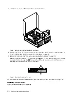
8. Pivot the optical drive bay upward and connect the card reader cable to one of the USB connectors on
the system board. See “Locating parts on the system board” on page 76.
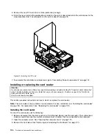
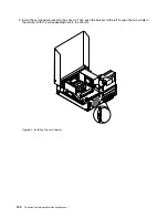
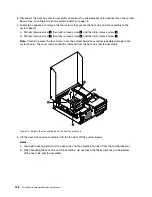
9. Reinstall the front bezel. See “Removing and reinstalling the front bezel” on page 120.
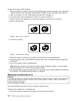
Note:
You might have to remove the card reader cover
2
from the front bezel. To remove the card read
cover, pivot the two retaining clips
1
that secure the card reader cover outwards and then completely
disengage the card reader cover from the front bezel.
Figure 62. Removing the card reader cover
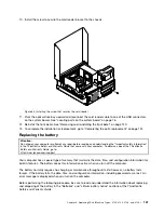
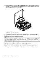
10. To complete the installation or replacement, go to “Completing the parts replacement” on page 157.
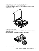
Replacing the card reader
To replace the card reader, do the following:
128
ThinkCentre Hardware Maintenance Manual
Summary of Contents for ThinkCentre M76
Page 6: ...2 ThinkCentre Hardware Maintenance Manual ...
Page 13: ...Chapter 2 Safety information 9 ...
Page 14: ... 18 kg 37 lb 32 kg 70 5 lb 55 kg 121 2 lb 10 ThinkCentre Hardware Maintenance Manual ...
Page 18: ...14 ThinkCentre Hardware Maintenance Manual ...
Page 19: ...1 2 Chapter 2 Safety information 15 ...
Page 20: ...1 2 16 ThinkCentre Hardware Maintenance Manual ...
Page 26: ...22 ThinkCentre Hardware Maintenance Manual ...
Page 27: ...1 2 Chapter 2 Safety information 23 ...
Page 31: ...Chapter 2 Safety information 27 ...
Page 32: ...1 2 28 ThinkCentre Hardware Maintenance Manual ...
Page 36: ...32 ThinkCentre Hardware Maintenance Manual ...
Page 40: ...36 ThinkCentre Hardware Maintenance Manual ...
Page 74: ...70 ThinkCentre Hardware Maintenance Manual ...
Page 116: ...112 ThinkCentre Hardware Maintenance Manual ...
Page 208: ...204 ThinkCentre Hardware Maintenance Manual ...
Page 213: ......
Page 214: ...Part Number 0A94225 Printed in USA 1P P N 0A94225 0A94225 ...