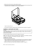

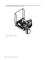

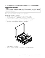


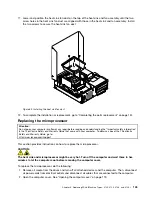


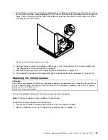


6. Remove the two screws that secure the heat sink fan duct. Then remove the heat sink fan duct from
the failing heat sink and fan assembly.
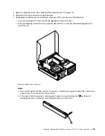
Figure 76. Removing the heat sink fan duct
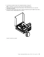
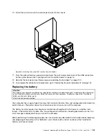
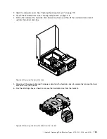
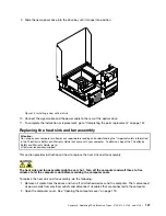
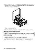
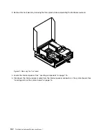
7. Place the new heat sink and fan assembly on the system board so that the four screws are aligned
with the corresponding holes in the system board. Make sure that you properly place the new heat
sink and fan assembly so that you can easily connect the new heat sink and fan assembly cable to the
microprocessor fan connector on the system board.
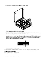
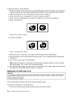
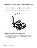
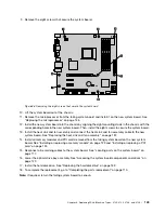
8. Follow this sequence to install the four screws to secure the new heat sink and fan assembly, as shown
in Figure 75 “Screws that secure the heat sink and fan assembly” on page 138:
a. Partially tighten screw
1
, then fully tighten screw
2
, and then fully tighten screw
1
.
b. Partially tighten screw
3
, then fully tighten screw
4
, and then fully tighten screw
3
.
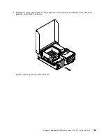
9. Connect the new heat sink and fan assembly cable to the microprocessor fan connector on the system
board. See “Locating parts on the system board” on page 76.
Chapter 9
.
Replacing FRUs (Machine Types: 3120, 3122, 3126, and 3128.)
139
Summary of Contents for ThinkCentre M76
Page 6: ...2 ThinkCentre Hardware Maintenance Manual ...
Page 13: ...Chapter 2 Safety information 9 ...
Page 14: ... 18 kg 37 lb 32 kg 70 5 lb 55 kg 121 2 lb 10 ThinkCentre Hardware Maintenance Manual ...
Page 18: ...14 ThinkCentre Hardware Maintenance Manual ...
Page 19: ...1 2 Chapter 2 Safety information 15 ...
Page 20: ...1 2 16 ThinkCentre Hardware Maintenance Manual ...
Page 26: ...22 ThinkCentre Hardware Maintenance Manual ...
Page 27: ...1 2 Chapter 2 Safety information 23 ...
Page 31: ...Chapter 2 Safety information 27 ...
Page 32: ...1 2 28 ThinkCentre Hardware Maintenance Manual ...
Page 36: ...32 ThinkCentre Hardware Maintenance Manual ...
Page 40: ...36 ThinkCentre Hardware Maintenance Manual ...
Page 74: ...70 ThinkCentre Hardware Maintenance Manual ...
Page 116: ...112 ThinkCentre Hardware Maintenance Manual ...
Page 208: ...204 ThinkCentre Hardware Maintenance Manual ...
Page 213: ......
Page 214: ...Part Number 0A94225 Printed in USA 1P P N 0A94225 0A94225 ...