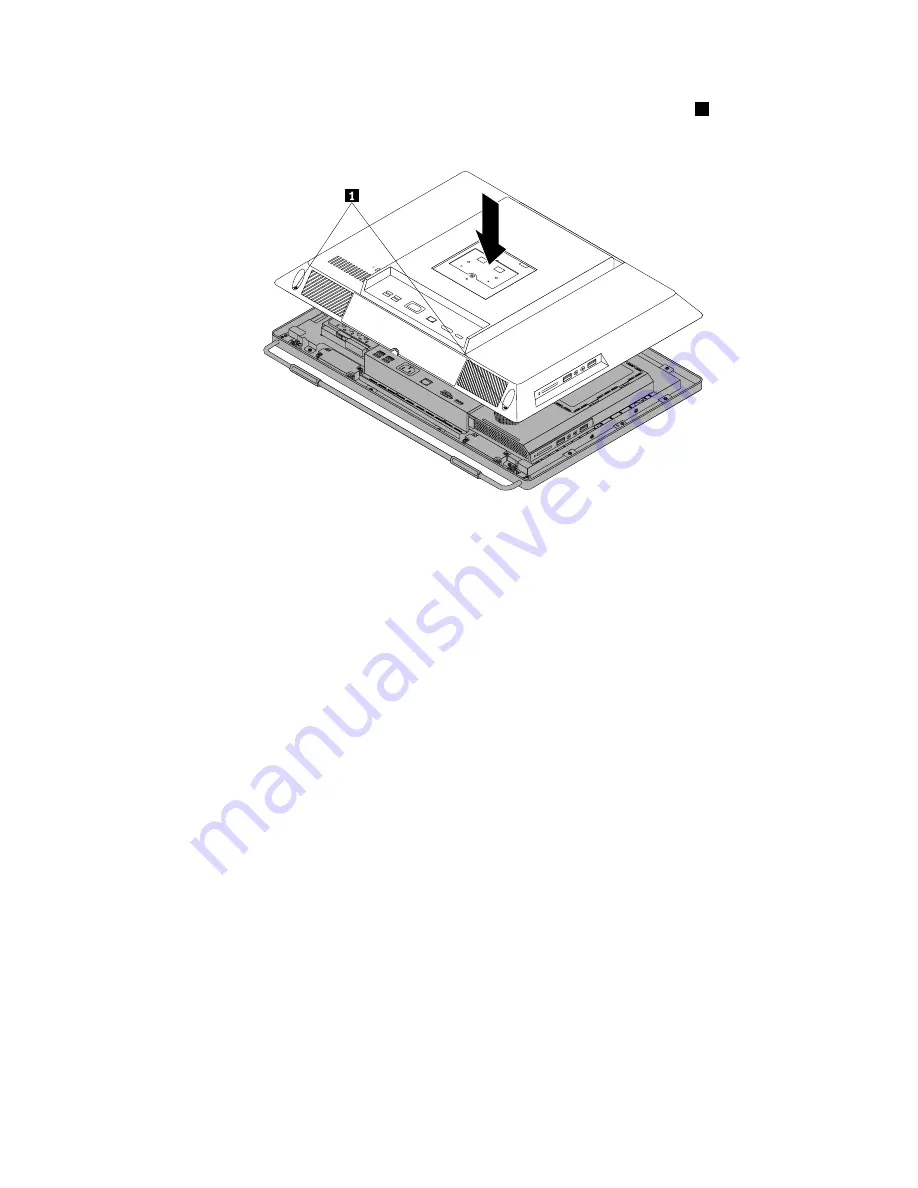
3. Lower and position the computer cover into place and then tighten the two screws
1
to secure the
computer cover.
Figure 48. Installing the computer cover
4. Reinstall the system stand and system stand hinge cover. See “Removing and reinstalling the system
stand” on page 90 and “Removing and reinstalling the system stand hinge cover” on page 88.
5. Lock the computer cover if you have an integrated cable lock.
6. Reconnect the external cables and power cord to the computer.
7. Depending on the parts you installed or replaced, you might need to confirm the updated information in
the Setup Utility program. Refer to Chapter 6 “Using the Setup Utility program” on page 57.
Note:
In most areas of the world, Lenovo requires the return of the defective Customer Replaceable Unit
(CRU). Information about this will come with the CRU or will come a few days after the CRU arrives.
Chapter 8
.
Replacing FRUs
125
Summary of Contents for ThinkCentre M71z
Page 2: ......
Page 8: ...2 ThinkCentre Hardware Maintenance Manual ...
Page 15: ...Chapter 2 Safety information 9 ...
Page 19: ...Chapter 2 Safety information 13 ...
Page 20: ...1 2 14 ThinkCentre Hardware Maintenance Manual ...
Page 21: ...Chapter 2 Safety information 15 ...
Page 27: ...Chapter 2 Safety information 21 ...
Page 31: ...Chapter 2 Safety information 25 ...
Page 38: ...32 ThinkCentre Hardware Maintenance Manual ...
Page 62: ...56 ThinkCentre Hardware Maintenance Manual ...
Page 132: ...126 ThinkCentre Hardware Maintenance Manual ...
Page 316: ...310 ThinkCentre Hardware Maintenance Manual ...
Page 320: ...314 ThinkCentre Hardware Maintenance Manual ...
Page 325: ......
Page 326: ...Part Number 0B03457 Printed in USA 1P P N 0B03457 0B03457 ...


