

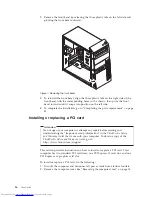


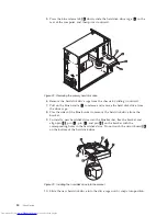


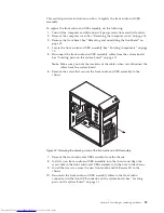


6.
Carefully remove the four screws
1
that secure the heat sink and fan
assembly to the system board.
Note:
Carefully remove the four screws from the system board to avoid any
possible damage to the system board. The four screws cannot be
removed from the heat sink and fan assembly.
7.
Lift the failing heat sink and fan assembly off the system board.
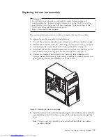
Notes:
a.
You might have to gently twist the heat sink and fan assembly to free it
from the microprocessor.
b.
Do not touch the thermal grease while handling the heat sink and fan
assembly.
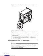
8.
Position the new heat sink and fan assembly on the system board so that the
four screws are aligned with the holes on the system board.
Note:
Position the new heat sink and fan assembly so that the heat sink and
fan assembly cable is toward the microprocessor fan connector on the
system board.
9.
Alternate tightening each screw a small and equal amount until the heat sink
and fan assembly is secured to the system board. Do not over-tighten the
screws.
10.
Connect the heat sink and fan assembly cable to the microprocessor fan
connector on the system board. See “Locating parts on the system board” on
page 11.
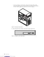
Figure 21. Removing the heat sink and fan assembly
28
User Guide
Summary of Contents for ThinkCentre 3349
Page 2: ......
Page 3: ...ThinkCentre User Guide ...
Page 6: ...European conformance CE mark 76 Trademarks 76 Index 77 iv User Guide ...
Page 8: ...vi User Guide ...
Page 56: ...48 User Guide ...
Page 72: ...64 User Guide ...
Page 82: ...74 User Guide ...
Page 88: ...80 User Guide ...
Page 89: ......
Page 90: ...Part Number 71Y7146 Printed in USA 1P P N 71Y7146 ...