background image

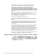
Taiwanese


Class


A


warning


statement


Lenovo


product


service


information


for


Taiwan


Chinese


Class


A


warning


statement


Korean


Class


A


warning


statement


Appendix.


Notices


77

Summary of Contents for TD100 - THINKSERVER 2.0G 2GB DVD 670W 6X7 TFF

Page 1: ...ThinkServer TD100 and TD100x Types 4203 4204 4205 4206 6398 6399 6419 and 6429 User Guide ...

Page 2: ......

Page 3: ...ThinkServer TD100 and TD100x Types 4203 4204 4205 4206 6398 6399 6419 and 6429 User Guide ...

Page 4: ... rights reserved LENOVO products data computer software and services have been developed exclusively at private expense and are sold to governmental entities as commercial items as defined by 48 C F R 2 101 with limited and restricted rights to use reproduction and disclosure LIMITED AND RESTRICTED RIGHTS NOTICE If products data computer software or services are delivered pursuant a General Servic...

Page 5: ... reliability guidelines 21 Working inside the server with the power on 22 Handling static sensitive devices 22 Removing the bezel 24 Removing the side cover 25 Removing the front fan cage assembly 27 Installing a memory module 28 Installing a drive 34 Installing a hot swap hard disk drive 35 IDs for hot swap hard disk drives 37 Installing a simple swap SATA hard disk drive TD100 models only 38 Pow...

Page 6: ...for Work gloss statement 74 Electronic emissions notices 74 Federal Communications Commission FCC statement 74 Industry Canada Class A emission compliance statement 74 Avis de conformité à la réglementation d Industrie Canada 74 Australia and New Zealand Class A statement 75 United Kingdom telecommunications safety requirement 75 European Union EMC Directive conformance statement 75 German Class A...

Page 7: ...een lue turvaohjeet kohdasta Safety Information Avant d installer ce produit lisez les consignes de sécurité Vor der Installation dieses Produkts die Sicherheitshinweise lesen Prima di installare questo prodotto leggere le Informazioni sulla Sicurezza Les sikkerhetsinformasjonen Safety Information før du installerer dette produktet Antes de instalar este produto leia as Informações sobre Segurança...

Page 8: ...ocument For example if a caution statement is labeled Statement 1 translations for that caution statement are in the Safety Information document under Statement 1 Be sure to read all caution and danger statements in this document before you perform the procedures Read any additional safety information that comes with any optional device before you install the device vi ThinkServer TD100 and TD100x...

Page 9: ...equipment when there is evidence of fire water or structural damage v Disconnect the attached power cords telecommunications systems networks and modems before you open the device covers unless instructed otherwise in the installation and configuration procedures v Connect and disconnect cables as described in the following table when installing moving or opening covers on this product or attached...

Page 10: ...ame module type made by the same manufacturer The battery contains lithium and can explode if not properly used handled or disposed of Do not v Throw or immerse into water v Heat to more than 100 C 212 F v Repair or disassemble Dispose of the battery as required by local ordinances or regulations viii ThinkServer TD100 and TD100x Types 4203 4204 4205 4206 6398 6399 6419 and 6429 User Guide ...

Page 11: ... the device v Use of controls or adjustments or performance of procedures other than those specified herein might result in hazardous radiation exposure DANGER Some laser products contain an embedded Class 3A or Class 3B laser diode Note the following Laser radiation when open Do not stare into the beam do not view directly with optical instruments and avoid direct exposure to the beam Class 1 Las...

Page 12: ...he power switch on the power supply do not turn off the electrical current supplied to the device The device also might have more than one power cord To remove all electrical current from the device ensure that all power cords are disconnected from the power source 1 2 x ThinkServer TD100 and TD100x Types 4203 4204 4205 4206 6398 6399 6419 and 6429 User Guide ...

Page 13: ...pect a problem with one of these parts contact a service technician Statement 12 CAUTION The following label indicates a hot surface nearby Statement 13 DANGER Overloading a branch circuit is potentially a fire hazard and a shock hazard under certain conditions To avoid these hazards ensure that your system electrical requirements do not exceed branch circuit protection requirements Refer to the i...

Page 14: ...tement 15 CAUTION Make sure that the rack is secured properly to avoid tipping when the server unit is extended xii ThinkServer TD100 and TD100x Types 4203 4204 4205 4206 6398 6399 6419 and 6429 User Guide ...

Page 15: ...t is in PDF on the ThinkServer Documentation DVD It contains translated caution and danger statements Each caution and danger statement that appears in the documentation has a number that you can use to locate the corresponding statement in your language in the Safety Information document v Hardware Maintenance Manual This document is available in English in PDF on the ThinkServer Documentation DV...

Page 16: ... provide important tips guidance or advice v Important These notices provide information or advice that might help you avoid inconvenient or problem situations v Attention These notices indicate potential damage to programs devices or data An attention notice is placed just before the instruction or situation in which damage could occur v Caution These statements indicate situations that can be po...

Page 17: ... the system board with RJ 45 Ethernet port v Six port Serial ATA controller v Integrated RAID capability HostRAID v Two serial ports v One parallel port v Four Universal Serial Bus USB v2 0 ports two on front and two on rear v Keyboard port v Mouse port v ATA 100 single channel IDE controller bus mastering v ATI ES1000 video controller Compatible with SVGA and VGA 16 MB SDRAM video memory Diagnost...

Page 18: ...7 in Weight approximately 34 kg 75 lb when fully configured or 20 kg 42 lb minimum Racks are marked in vertical increments of 4 45 cm 1 75 inches Each increment is referred to as a unit or U A 1 U high device is 4 45 cm 1 75 inches tall Integrated functions v Baseboard management controller Intelligent Platform Management Interface IPMI 2 0 compliant v Easy LED diagnostics v ServeRAID 8k 512 MB wi...

Page 19: ...aintain high performance while limiting downtime Through a single console you can monitor and configure alerts for security and performance perform hardware failure prediction deploy operating systems and software and monitor software licenses You can download and install the EasyManage software from the Lenovo Support Web site http www lenovo com support v ThinkServer EasyStartup DVD The Lenovo T...

Page 20: ...wo 835 watt power supplies which provide redundancy and hot swap capability for a typical configuration If the maximum load on the server is less than 835 watts and a problem occurs with one of the power supplies the other power supply can meet the power requirements v ServeRAID support Some models support ServeRAID adapters to create redundant array of independent disks RAID configurations Some m...

Page 21: ... of POST failures v Hot swap Serial Attached SCSI SAS and hot swap Serial ATA SATA hard disk drives v Integrated Ethernet controller v Support for an optional IBM Remote Supervisor Adapter II SlimLine v Key lock support for physical security v Memory change messages posted to the error log v Baseboard management controller BMC or service processor v Power management v Power on self test POST v Rea...

Page 22: ...front of the hot swap server models 1 System power LED 6 CD eject or DVD eject button 2 Power control button 7 Hot swap hard disk drive status LED amber 3 Hard disk drive activity LED 8 Hot swap hard disk drive activity LED green 4 System error LED 9 CD or DVD drive activity LED green 5 USB connectors 10 Front information panel 8 ThinkServer TD100 and TD100x Types 4203 4204 4205 4206 6398 6399 641...

Page 23: ...ff but still connected to ac power When this LED is off it indicates that ac power is not present or the power supply or the LED itself has failed Power control button Press this button to turn the server on and off manually Hard disk drive activity LED When this LED is flashing rapidly it indicates that a hard disk drive is in use System error LED When this amber LED is lit it indicates that a sy...

Page 24: ...ne next to the drive connector The backplane is the printed circuit board behind drive bays 4 through 7 Hot swap hard disk drive status LED hot swap models only On some server models each hot swap hard disk drive has an amber status LED If this amber status LED is lit it indicates that the associated hard disk drive has failed If an optional ServeRAID adapter is installed in the server and the LED...

Page 25: ...connectors 3 and 4 3 DC power LEDs 10 RJ45 Ethernet 10 100 1000 4 Mouse connector 11 RJ45 Ethernet 10 100 for Remote Supervisor Adapter II SlimLine 5 Keyboard connector 12 NMI button 6 Serial 1 COM 1 connector 13 Serial 2 COM 2 connector 7 Parallel connector The following illustration shows the connectors on the rear of the non hot swap power supply models For more information about these connecto...

Page 26: ... operation both the ac and dc power LEDs are lit For any other combination of LEDs see the Hardware Maintenance Manual DC power LED hot swap power supply models only This green LED provides status information about the power supply During typical operation both the ac and dc power LEDs are lit For any other combination of LEDs see the Hardware Maintenance Manual Mouse connector Connect a mouse dev...

Page 27: ...flashes to indicate that the server is connected to ac power but not turned on Turning on the server Approximately 20 seconds after the server is connected to ac power the power control button becomes active and one or more fans might start running to provide cooling while the server is connected to power You can turn on the server and start the operating system by pressing the power control butto...

Page 28: ...t all power cords are disconnected from the power source 1 2 The server can be turned off in any of the following ways v You can turn off the server from the operating system if your operating system supports this feature After an orderly shutdown of the operating system the server will be turned off automatically v You can press the power control button to start an orderly shutdown of the operati...

Page 29: ... might differ slightly from your hardware 31 1 Hot swap power supply some models 17 Hot swap fan 2 Fixed power supply some models 18 Processor baffle 3 Control panel assembly 19 System board 4 Drive bay EMC shield 20 ServeRAID 8k l TD100 or ServeRAID 8k TD100x 5 USB cable assembly 21 Voltage regulator module VRM 6 CD DVD drive 22 Cover 7 Hot swap drive 23 Heat sink filler 8 CD DVD drive trim piece...

Page 30: ...ckplane power 2 Power 11 Simple swap SATA backplate 3 Power 12 Hot swap SAS SATA signal 4 USB tape 13 Hot swap main fan 5 Front panel 14 Hot swap fan redundant 6 Primary IDE 15 Battery 7 Front USB 16 Reserved 8 Microprocessor 1 17 Serial 2 COM 2 header 9 Microprocessor 2 18 Rear fan 16 ThinkServer TD100 and TD100x Types 4203 4204 4205 4206 6398 6399 6419 and 6429 User Guide ...

Page 31: ... 8 9 10 11 12 DIMM LEDs 1 Mouse connector 6 USB connectors 2 2 Keyboard connector 7 RJ45 Ethernet 10 100 1000 connector 3 Serial 1 COM 1 connector 8 RJ45 Ethernet 10 100 for Remote Supervisor Adapter II SlimLine connector 4 Parallel connector 9 NMI button 5 Video connector 10 Serial 2 COM 2 connector Chapter 2 Installing optional devices 17 ...

Page 32: ...nnector 8 PCI X 64 bit 133 MHz connector 3 Microprocessor 2 connector 9 PCI Express x8 x8 connector 4 VRM connector 10 PCI Express x8 x4 connector 5 Battery 11 System management Ethernet connector 6 RAID adapter 12 DIMM connectors 6 System board switches The following illustration shows the SW4 switch Boot block Clear CMOS 1 on the system board 18 ThinkServer TD100 and TD100x Types 4203 4204 4205 ...

Page 33: ...s on 1 this is the normal mode v When this switch is toggled to On this enables the system to recover if the BIOS code becomes damaged See the Hardware Maintenance Manual for information about recovering from a BIOS update failure 2 Clear CMOS v When this switch is on 2 this is the normal mode This keeps the CMOS data v When this switch is toggled to On this clears the CMOS data which clears the p...

Page 34: ...n page v the guidelines in Working inside the server with the power on on page 22 and Handling static sensitive devices on page 22 This information will help you work safely v When you install your new server take the opportunity to download and apply the most recent firmware updates This step will help to ensure that any known issues are addressed and that your server is ready to function at maxi...

Page 35: ...the muscles in your back lift by standing or by pushing up with your leg muscles v Make sure that you have an adequate number of properly grounded electrical outlets for the server monitor and other devices v Back up all important data before you make changes to disk drives v Have a small flat blade screwdriver available v You do not have to turn off the server to install or replace hot swap power...

Page 36: ...side a server that is turned on v Avoid wearing loose fitting clothing on your forearms Button long sleeved shirts before working inside the server do not wear cuff links while you are working inside the server v Do not allow your necktie or scarf to hang inside the server v Remove jewelry such as bracelets necklaces rings and loose fitting wrist watches v Remove items from your shirt pocket such ...

Page 37: ...e the device from its package and install it directly into the server without setting down the device If it is necessary to set down the device put it back into its static protective package Do not place the device on the server cover or on a metal surface v Take additional care when handling devices during cold weather Heating reduces indoor humidity and increases static electricity Chapter 2 Ins...

Page 38: ...orrectly see the Hardware Maintenance Manual for diagnostic information To remove the bezel complete the following steps Note The illustrations in this document might differ slightly from your hardware 1 Read the safety information that begins on page v and Installation guidelines on page 20 2 Unlock the side cover Note You must unlock the side cover to remove the bezel 3 Position your finger on t...

Page 39: ... the operating system starts if an operating system is installed or that a 19990305 error code is displayed indicating that an operating system was not found but the server is otherwise working correctly If the server is not working correctly see the Hardware Maintenance Manual for diagnostic information To remove the server side cover complete the following steps 1 Read the safety information tha...

Page 40: ...talling the side cover on page 57 Attention For proper cooling and airflow replace the cover before turning on the server Operating the server for extended periods of time more than 30 minutes with the cover removed might damage server components 26 ThinkServer TD100 and TD100x Types 4203 4204 4205 4206 6398 6399 6419 and 6429 User Guide ...

Page 41: ...ower supply Press down on the orange release lever and pull the power supply out of the bay using the handle b Lift up the power supply cage handle and pull the power supply cage assembly all the way up until the retainer latch locks the cage in place on the chassis v Non hot swap models lift up the power supply cage handle and pull the power supply cage assembly all the way up until the retainer ...

Page 42: ...100 models Do not install DIMMs in these four connectors and do not remove the DIMM thermal baffles installed in these connectors unless you need to replace the system board v When installing multiple pairs always install the DIMMs with the most capacity in the first slots For example if you had a pair of 1 GB DIMMs and a pair of 4 GB DIMMs you would install the 4 GB DIMMs in slots 1 and 4 v The m...

Page 43: ...er to eight or 12 DIMMs the DIMMs that are next to each other for example DIMM connector 1 and DIMM connector 4 within the channels of a branch must be identical in size type speed and technology However the DIMMs in the connectors above or below each other within the channels of a branch do not have to be identical to each other for example the DIMMs in DIMM connector 1 and DIMM connector 2 Both ...

Page 44: ...M connector 7 and DIMM connector 10 they do not have to be the same size speed type and technology as the DIMMs in DIMM connector 1 and DIMM connector 4 However the size speed type and technology of the DIMMs that you install in DIMM connector 7 and DIMM connector 10 must match each other The following table shows the DIMM upgrade configuration sequence for operating in non mirroring mode normal m...

Page 45: ...s a Remove the hot swap power supply Press down on the orange release lever and pull the power supply out of the bay using the handle b Lift up the power supply cage handle and pull the power supply cage assembly all the way up until the retainer latch locks the cage in place on the chassis v Non hot swap models lift up the power supply cage handle 2 and pull the power supply cage assembly 1 all t...

Page 46: ...the DIMM straight down into the connector by applying pressure on both ends of the DIMM simultaneously The retaining clips snap into the locked position when the DIMM is firmly seated in the connector If there is a gap between the DIMM and the retaining clips the DIMM has not been correctly installed Open the retaining clips remove the DIMM and then reinsert it 1 DIMM 1 connector 7 DIMM 7 2 DIMM 2...

Page 47: ...power supply cage release tab 1 and rotate the power supply cage assembly into the chassis 13 If you have a hot swap model reinstall the hot swap power supplies If you have other options to install or remove do so now otherwise go to Completing the installation on page 55 Chapter 2 Installing optional devices 33 ...

Page 48: ...ing are illustrations of the server and the location of the drive bays Your hardware might differ depending on the model The following is an illustration of the hot swap server models TD100x 1 Bay 1 7 Bay 7 2 Bay 2 8 Bay 8 3 Bay 3 9 Bay 9 4 Bay 4 10 Bay 10 5 Bay 5 11 Bay 11 6 Bay 6 34 ThinkServer TD100 and TD100x Types 4203 4204 4205 4206 6398 6399 6419 and 6429 User Guide ...

Page 49: ...drives are examples of removable media drives You can install removable media drives in bays 1 2 and 3 only v To install a 3 5 inch drive in a 5 25 inch bay you must use a 5 25 inch conversion kit v The electromagnetic interference EMI integrity and cooling of the server are protected by having all bays and PCI PCI Express and PCI X slots covered or occupied When you install a drive or PCI PCI Exp...

Page 50: ... need the 4 drive backplane option kit v Remove any dust shields from the signal cable connectors before installing the signal cables Attention Static electricity that is released to internal server components when the server is powered on might cause the server to stop which could result in the loss of data To avoid this potential problem always use an electrostatic discharge wrist strap or other...

Page 51: ...configured for RAID operation using an optional ServeRAID adapter you might have to reconfigure your disk arrays after installing hard disk drives See the ServeRAID documentation on the IBM ServeRAID Support CD for additional information about RAID operation 6 If you are installing additional hot swap hard disk drives do so now If you have other options to install or remove do so now otherwise go ...

Page 52: ...page v and Installation guidelines on page 20 2 Turn off the server and peripheral devices and disconnect all external cables and power cords 3 Unlock the side cover you cannot open or remove the bezel without unlocking the side cover 4 Remove the bezel see Removing the bezel on page 24 5 Touch the static protective package that contains the drive to any unpainted metal surface on the server then ...

Page 53: ...you replace any drives remember which cable is attached to which drive v If you have only one IDE device on a cable it must be set as a master device v If two IDE devices are used on a single cable one must be designated as the master device and the other as the subordinate device otherwise the server might not recognize some of the IDE devices The master and subordinate designation is determined ...

Page 54: ...that comes with these devices For a list of supported options for the server see http www lenovo com thinkserver Installing an adapter The following notes describe the types of adapters that the server supports and other information that you must consider when installing an adapter The type of adapters that the server supports might vary depending on your server model v Locate the documentation th...

Page 55: ...s or switches if there are any Route the adapter cables before you install the adapter 4 Rotate the rear adapter retention bracket to the open unlocked position 5 If you are installing a full length adapter press on the release lever on the right side of the front adapter retention bracket to release the retaining tab on the left side of the bracket 6 Remove the screw that secures the expansion sl...

Page 56: ... options to install or remove do so now otherwise go to Completing the installation on page 55 Installing a microprocessor The following notes describe the type of microprocessor that the server supports and other information that you must consider when installing a microprocessor v The server comes with one microprocessor installed but supports up to two microprocessors Note A microprocessor must...

Page 57: ...ation of the microprocessor connectors and the VRM connector To install an additional microprocessor complete the following steps 1 Read the safety information beginning on page v and Installation guidelines on page 20 2 Turn off the server and disconnect all power cords and external cables see Turning off the server on page 14 then unlock and remove the server cover see Removing the side cover on...

Page 58: ...ention v Do not use excessive force when pressing the microprocessor into the socket v Make sure that the microprocessor is oriented and aligned with land number 1 in the socket before you try to close the lever e Align the microprocessor 1 with the socket note the alignment mark 2 and the position of the notches then carefully place the microprocessor on the socket 4 and close the microprocessor ...

Page 59: ...2 VRM 2 Microprocessor 2 4 Microprocessor release lever d Slide the flange of the heat sink into the opening beneath the retainer bracket 1 Heat sink locking lever 2 Microprocessor 3 Heat sink Chapter 2 Installing optional devices 45 ...

Page 60: ...lies only to server models that have hot swap power supplies If you have a non hot swap model it comes with only one 670 watt power supply which must be replaced only by a service technician v The server comes with one power supply v The redundant mode requires two 835 watt hot swap power supplies in the server You must install an additional redundant power and cooling option kit the option kit co...

Page 61: ... is released to internal server components when the server is powered on might cause the server to halt which could result in the loss of data To avoid this potential problem always use an electrostatic discharge wrist strap or other grounding system when working inside the server with the power on 2 Disconnect the power cord from the power supply that is to be removed 3 If you are replacing a pow...

Page 62: ...atic protective package that contains the hot swap power supply to any unpainted metal surface on the server then remove the power supply from the package and place it on a static protective surface 6 Place the power supply into the bay guides 1 Power supply filler 2 Release latch 3 Power supply 48 ThinkServer TD100 and TD100x Types 4203 4204 4205 4206 6398 6399 6419 and 6429 User Guide ...

Page 63: ...ng steps 1 Review the safety information that begins on page v and Installation guidelines on page 20 Attention Static electricity that is released to internal server components when the server is powered on might cause the server to halt which could result in the loss of data To avoid this potential problem always use an electrostatic discharge wrist strap or other grounding system when working i...

Page 64: ...er TD100 models The IBM ServeRAID 8k l adapter must be installed in its dedicated connector on the system board See the illustration in the following procedure for the location of the connector on the system board The ServeRAID 8k l adapter is not cabled to the system board and no rerouting of the SCSI cable is required To install the ServeRAID 8k l adapter complete the following steps 1 Read the ...

Page 65: ...nector on the system board The ServeRAID 8k adapter is not cabled to the system board and no rerouting of the SAS or SATA cable is required on many models However if you install this optional ServeRAID 8k adapter in simple swap SATA models some recabling is required To install the ServeRAID 8k adapter complete the following steps 1 Read the safety information that begins on page v and Handling sta...

Page 66: ... adapter firmly into the connector 8 Slide the battery pack mounting tabs into the battery pack mounting clips on the chassis wall 1 Battery cable 4 Battery mounting clips 2 Battery 5 Battery cable connector 3 Battery mounting tabs 6 RAID controller 9 Plug the battery pack cable into the battery cable connector on the ServeRAID 8k adapter 52 ThinkServer TD100 and TD100x Types 4203 4204 4205 4206 6...

Page 67: ...oard See System board internal connectors on page 16 for the location of these connectors on the system board Note Remove the dust shield 1 if one is present from the Hot swap SAS SATA 1 signal connector 2 on the system board before installing the signal cable Carefully grasp the dust shield and pull it out of the signal connector b Connect the RAID level 5 enabler plug that came with the system 1...

Page 68: ...RAID 8k Controller into the simple swap SATA model 1 SAS SATA backplane 1 connector 2 RAID level 5 enabler plug 3 SAS SATA backplane 2 connector 4 Hot swap SAS SATA 1 cable 11 If you have other options to install or remove do so now 12 Replace the side cover see Reinstalling the side cover on page 57 Go to Completing the installation on page 55 54 ThinkServer TD100 and TD100x Types 4203 4204 4205 ...

Page 69: ...place the bezel complete the following steps 1 Align the hinge assembly with the hinge holes on the chassis 1 Bezel 2 Retention tabs 3 Hinge assembly 2 Push the hinges into the holes on the chassis until they snap into place 3 If however the bezel was removed by detaching the sliding hinge mount from the hinge assembly using the breakaway method as the bezel was designed to do complete the followi...

Page 70: ...lace b Align the sliding hinge mount 1 with the hinge pin 2 on the hinge assembly on the chassis c Press the sliding hinge mount against the hinge pin until the sliding hinge mount snaps onto the hinge pin 4 Close the bezel 56 ThinkServer TD100 and TD100x Types 4203 4204 4205 4206 6398 6399 6419 and 6429 User Guide ...

Page 71: ...omponents are installed and seated correctly and that you have not left loose tools or parts inside the server Also make sure that all internal cables are correctly routed 2 Insert the bottom edges of the cover into the inside of the chassis and rotate the cover toward the server 3 Press down on the cover release latch and close the cover to secure it in place 4 Lock the side cover Chapter 2 Insta...

Page 72: ...f the hot swap power supply models with optional redundant power 1 Power cord connectors 8 Video connector 2 AC power LEDs 9 USB connectors 3 and 4 3 DC power LEDs 10 RJ45 Ethernet 10 100 1000 connector 4 Mouse connector 11 RJ45 Ethernet 10 100 for Remote Supervisor Adapter II SlimLine connector 5 Keyboard connector 12 NMI button 6 Serial 1 COM 1 connector 13 Serial 2 COM 2 connector 7 Parallel co...

Page 73: ...etup Utility program starts automatically so that you can save the new configuration settings For additional information see Using the Configuration Setup Utility program on page 61 Some options have device drivers that you must install For information about installing device drivers see the documentation that comes with each option If the server has a RAID adapter and you have installed or remove...

Page 74: ...Note If you are attaching an external device see the documentation that comes with the device for information about cabling Installing the server in a rack To convert the server from a tower model to a rack model you must use a Tower to Rack Kit You can then install the server in a rack cabinet To order a Tower to Rack Kit for the server contact your Lenovo marketing representative or authorized r...

Page 75: ...ce v ThinkServer EasyManage products ThinkServer EasyManage Core Server and ThinkServer EasyManage Agent work together to provide centralized hardware and software inventory management and secure automated system management through a single console For more information about the EasyManage products see the Installation Guide v Integrated System Management Firmware Update TD100x only Use this utili...

Page 76: ...e of those changes are reflected in the system information you cannot change settings directly in the system information This choice is on the full Configuration Setup Utility menu only v Devices and I O Ports Select this choice to view or change device assignments and input output I O ports Select this choice to enable or disable the integrated SAS SATA controller and Ethernet controller and stan...

Page 77: ...word An administrator password is intended to be used by a system administrator it limits access to the full Configuration Setup Utility menu If an administrator password is set the full Configuration Setup Utility menu is available only if you type the administrator password at the password prompt Power on Password Select this choice to set change or delete a power on password v Start Options Sel...

Page 78: ...e IPMI specification version BMC Firmware Version This nonselectable item displays the mini BMC firmware version BMC Build Date This nonselectable item displays the date that the mini BMC code was built BMC Build Level This nonselectable item displays the version of the mini BMC code Existing Event Log number This nonselectable item displays the number of entries in the system event log BMC POST W...

Page 79: ...all system error messages that have been generated Use the arrow keys to move among pages in the log Run the diagnostic programs to get more information about the error codes See the Hardware Maintenance Manual on the ThinkServer Documentation DVD for instructions for solving the problems Select Clear BMC System Event Log to clear the mini BMC system event logs v Event Error Logs Select this choic...

Page 80: ...enu program is a built in menu driven configuration program that you can use to temporarily redefine the first startup device without changing settings in the Configuration Setup Utility program To use the Boot Menu program complete the following steps 1 Restart the server 2 Press F12 3 Select the startup device The next time the server is started it returns to the startup sequence that is set in ...

Page 81: ...firmware updates and SDR FRU updates and remotely manage a network Using the baseboard management controller configuration utility program Use the baseboard management controller configuration utility program to view or change the baseboard management controller configuration settings You can also use the utility program to save the configuration to a file for use on multiple servers Go to http ww...

Page 82: ... from the Select your product list 3 From Family list select ThinkServer TD100 and TD100x and click Continue 4 Click Downloads and drivers to download firmware updates 5 From the BMC software copy the files bmc exe and Init ini to a setup utility diskette To update the firmware run the executable program in the package Follow the instructions that come with the package 68 ThinkServer TD100 and TD1...

Page 83: ...erein these changes will be incorporated in new editions of the publication Lenovo may make improvements and or changes in the product s and or the program s described in this publication at any time without notice The products described in this document are not intended for use in implantation or other life support applications where malfunction may result in injury or death to persons The inform...

Page 84: ...es may be trademarks or service marks of others Important notes Processor speed indicates the internal clock speed of the microprocessor other factors also affect application performance CD or DVD drive speed is the variable read rate Actual speeds vary and are often less than the possible maximum When referring to processor storage real and virtual storage or channel volume KB stands for 1024 byt...

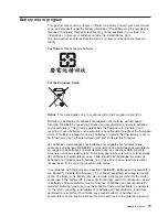
Page 85: ...r a los propietarios de equipos a reciclar sus productos de TI Se puede encontrar información sobre las ofertas de reciclado de productos de Lenovo en el sitio web de Lenovo http www lenovo com lenovo environment recycling Notice This mark applies only to countries within the European Union EU and Norway Appliances are labeled in accordance with European Directive 2002 96 EC concerning waste elect...

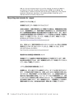
Page 86: ...E and minimize any potential effects of EEE on the environment and human health due to the potential presence of hazardous substances For additional WEEE information go to http www lenovo com lenovo environment Recycling statements for Japan 72 ThinkServer TD100 and TD100x Types 4203 4204 4205 4206 6398 6399 6419 and 6429 User Guide ...

Page 87: ...ballages pour batteries sont étiquetés conformément aux directives européennes 2006 66 EC norme relative aux batteries et accumulateurs en usage et aux batteries et accumulateurs usés Les directives déterminent la marche à suivre en vigueue dans l Union Européenne pour le retour et le recyclage des batteries et accumulateurs usés Cette étiquette est appliquée sur diverses batteries pour indiquer q...

Page 88: ...ated in a commercial environment This equipment generates uses and can radiate radio frequency energy and if not installed and used in accordance with the instruction manual may cause harmful interference to radio communications Operation of this equipment in a residential area is likely to cause harmful interference in which case the user will be required to correct the interference at his own ex...

Page 89: ...le protection against interference with licensed communication equipment Attention This is a Class A product In a domestic environment this product may cause radio interference in which case the user may be required to take adequate measures German Class A compliance statement Deutschsprachiger EU Hinweis Hinweis für Geräte der Klasse A EU Richtlinie zur Elektromagnetischen Verträglichkeit Dieses ...

Page 90: ...5022 Dies ist eine Einrichtung der Klasse A Diese Einrichtung kann im Wohnbereich Funkstörungen verursachen in diesem Fall kann vom Betreiber verlangt werden angemessene Maßnahmen durchzuführen und dafür aufzukommen Nach dem EMVG Geräte dürfen an Orten für die sie nicht ausreichend entstört sind nur mit besonderer Genehmigung des Bundesministers für Post und Telekommunikation oder des Bundesamtes ...

Page 91: ...Taiwanese Class A warning statement Lenovo product service information for Taiwan Chinese Class A warning statement Korean Class A warning statement Appendix Notices 77 ...

Page 92: ...78 ThinkServer TD100 and TD100x Types 4203 4204 4205 4206 6398 6399 6419 and 6429 User Guide ...

Page 93: ...nts in the server 15 major 15 configuration EasyStartup CD 61 updating 59 configuration programs Boot Menu 61 Broadcom NetXtreme Gigabit Ethernet controller 61 Configuration Setup Utility program 61 general 61 configuring the Ethernet controller 66 the server 61 connector adapter 18 battery 16 cable 58 Ethernet 13 external 10 11 17 internal 16 keyboard 12 memory 18 microprocessor 18 mouse 12 paral...

Page 94: ...ve continued status LED 10 heat output 3 4 hot plug adapter See adapter hot swap and hot plug devices adapters 50 hot swap drive backplane activity LED 10 SAS IDs 37 status LED 10 installation 35 specifications 3 hot swap fan installing 50 hot swap power supply installing 48 removing 47 replacing 46 safety 46 hot swap SAS drives cabling 40 hot swap SATA drives cabling 40 humidity 4 I IDs for SAS h...

Page 95: ...tallation sequence 29 modes Ethernet 67 mouse connector 12 N noise emissions 4 non hot swap power supply installing 46 notes 2 notes important 70 notices 69 notices and statements 2 O online publications 1 2 online spare memory 6 optional device installation guidelines 20 static sensitive 22 options adapters 40 41 connectors 11 18 drives 34 installing 20 memory modules 28 order of installation har...

Page 96: ...s 15 power features 13 specifications 3 ServeRAID 8k adapter installing 51 serviceability features 6 setup advanced 63 simple swap drives 38 simple swap SATA drives cabling 40 size 3 4 slots 4 specifications 4 statements and notices 2 static electricity 22 static sensitive devices handling 22 status LEDs 8 switches on the system board 18 system board connectors 11 12 58 59 external connectors 17 i...

Page 97: ......

Page 98: ...Part Number 46U0858 Printed in USA 1P P N 46U0858 ...

Reviews: