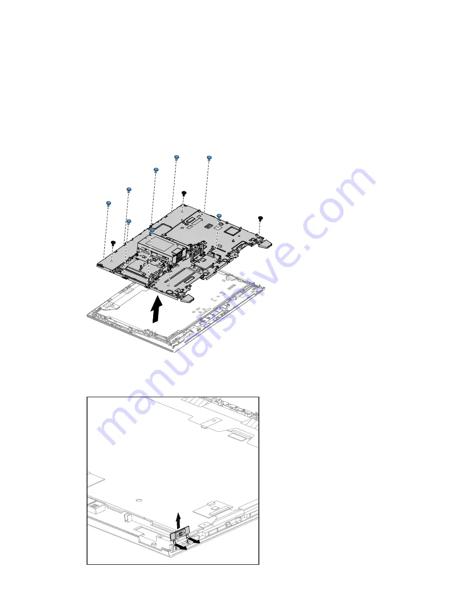
Step 13. Disconnect the LVDS cable from the connector on the LED panel.
Step 14. Disconnect the converter cable from the connector on the converter.
Step 15. Disconnect the front function board cable from the connector on the motherboard.
Step 16. Disconnect the front indicator board cable from the connector on the motherboard.
Step 17. Disconnect the power switch board cable from the connector on the motherboard.
Step 18. Remove the eight screws that secure the chassis to the front bezel.
Step 19. Remove the four screws secure the chassis to the LED panel bracket.
Step 20. Lift up the chassis gently as shown.
Step 21. Remove the converter cable from the connector on the LED panel.
Step 22. Push the pins that secure the power switch board to the front bezel, and then lift out the power
switch board as shown.
Chapter 8
.
Replacing hardware
61
Summary of Contents for IdeaCentre B345
Page 2: ......
Page 6: ...iv IdeaCentre B345 B545 All In OneHardware Maintenance Manual ...
Page 8: ...2 IdeaCentre B345 B545 All In OneHardware Maintenance Manual ...
Page 16: ...10 IdeaCentre B345 B545 All In OneHardware Maintenance Manual ...
Page 18: ...12 IdeaCentre B345 B545 All In OneHardware Maintenance Manual ...
Page 24: ...18 IdeaCentre B345 B545 All In OneHardware Maintenance Manual ...


