b.
Tighten screw
2
a small amount, then fully install screw
4
, and then
fully install screw
2
, as shown in Figure 19 on page 25.
10.
Connect the new heat sink and fan assembly cable to the microprocessor fan
connector on the system board. See “Locating parts on the system board” on
page 11.
11.
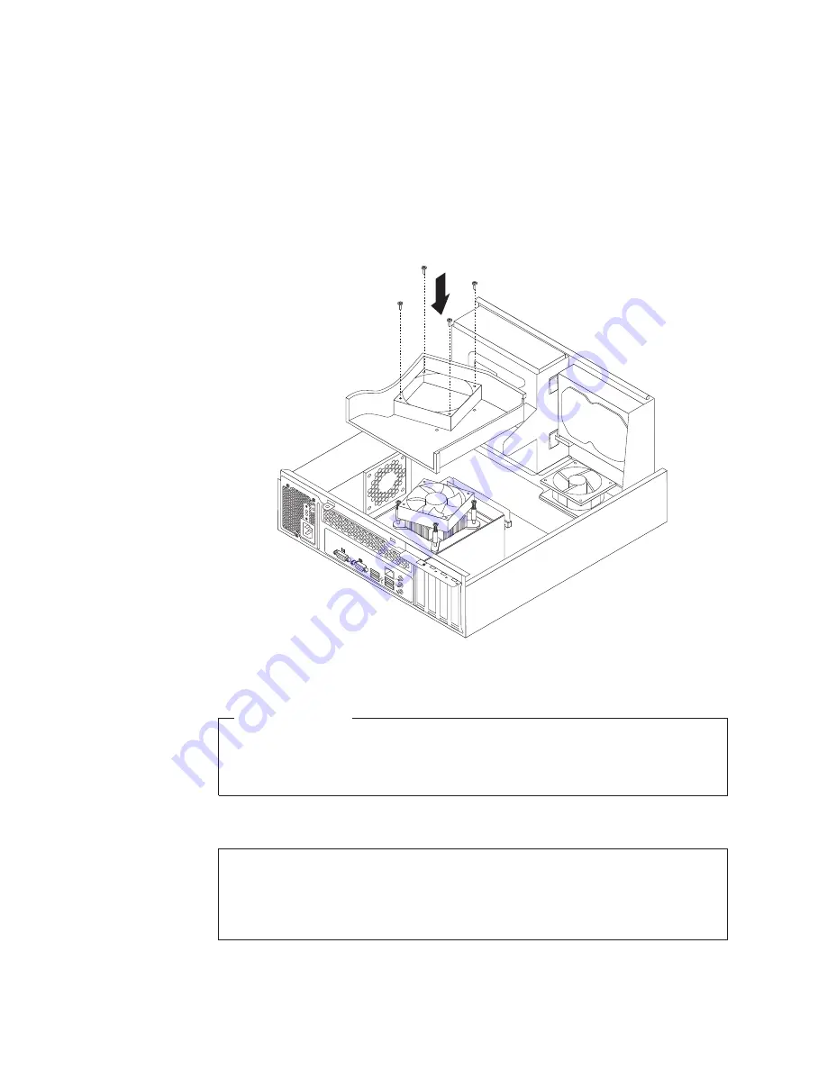
Position the heat sink fan duct on the top of the new heat sink and fan
assembly so that the four screw holes in the heat sink fan duct are aligned
with the corresponding holes in the new heat sink and fan assembly. Install
the four screws to secure the heat sink fan duct in place.
What to do next:
v
To work with another piece of hardware, go to the appropriate section.
v
To complete the replacement, go to “Completing the parts replacement” on
page 46.
Replacing the microprocessor
Attention
Do not open your computer or attempt any repair before reading and understanding the
“Important safety information” in the
ThinkCentre Safety and Warranty Guide
that came with
your computer. To obtain a copy of the
ThinkCentre Safety and Warranty Guide
, go to:
http://www.lenovo.com/support
This section provides instructions on how to replace the microprocessor.
Figure 20. Installing the heat sink fan duct
26
User Guide
Summary of Contents for 7844B4U
Page 1: ...Machine Types 0889 5023 and 7844 ThinkCentre User Guide ...
Page 2: ......
Page 3: ...ThinkCentre User Guide ...
Page 8: ...vi User Guide ...
Page 60: ...52 User Guide ...
Page 68: ...60 User Guide ...
Page 76: ...68 User Guide ...
Page 86: ...78 User Guide ...
Page 92: ...84 User Guide ...
Page 93: ......
Page 94: ...Part Number 89Y9113 Printed in USA 1P P N 89Y9113 ...


