
.
X70 Series Quick Guide
【
English
】
53R-X70003-2001
E
VESA mounting it to the wall
E
Placing on the desk
E
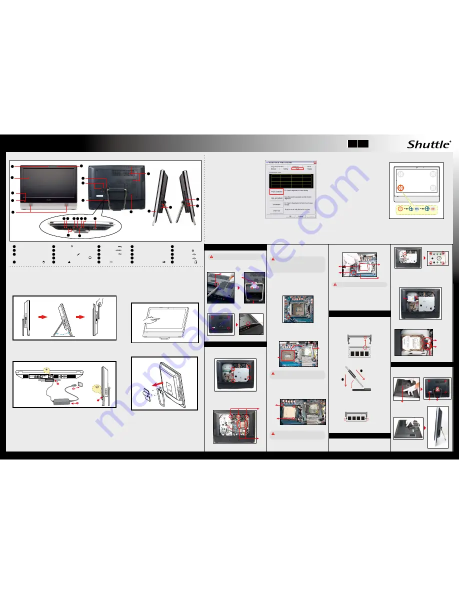
Front/Rear/Side View
Run the screen calibration
program and correct 4 point
locations on screen with the
panel.
Click
Start / All Programs
/ eGalax Touch
/ Configure Utility
Select
[Tools]
tab and click
[4 Points Calibration]
E
How to use the Touch Panel (Optional)
When the 4 points calibration completed,
press
[OK]
to continue.
E
4 Point Calibration (Optional)
X70 brings digital life for an easy touch experience.Experience
the ease of managing your digital life with a few touches.
The touch of your finger replaces the mouse and is all you need
to interact with the X70.
Touch and hold the center of the target.
Repeat on four corners and the screen will
adjust automatically.
E
Cleaning the screen
Follow these guidelines for cleaning the outside and handling the screen
of the computer:
Turn off the system and disconnect all cables.
Use a damp, or cleaning cloth, soft, lint-free cloth with gentle water only
and gently wipe the screen surface.
Do not spray liquid directly on the screen.
・
Touch = left-click on the mouse
・
Touch and hold = right-click on the mouse
Follow the steps (1~3) below to connect the AC adapter to the
DC in
jack.
Press the
Power Button
to turn on the system.
E
Powering on the system
Note : X70 can be mounted to a wall using a VESA
compatible 100 x 100mm wall/arm bracket.
If you are mounting your X70 to the wall, remove the cover
on the back of X70 first.
Unscrew three screws of the stand mount and remove the
stand.
The VESA standard lets users mount it on to walls easily.
Please refer to the user guide of the wall/arm mount kit you
bought to install it.
Note:
The product’s color and specification will depend upon the actually shipping product.
E
Safety Information
Read the following precautions before setting up a Shuttle X70.
Hold
OK
62R-X70000-0601 X70
English.Spanish.Korean.
Traditional Chinese.Japanese.
French. German Quick Guide
To place the machine on the desk and to carry it, do the following:
Place the X70 on a flat surface such as a table (Picture 1), and pull the stand
upwards to an angle of 30°, the support bracket can be opened to 60 degrees at
most(Picture 2). To carry or move your X70, turn back the angle to 0° (Picture 3).
Power
Button
4
DCIN
3.
2.
1.
Max 60
CAUTION 1.
Danger of explosion if battery is incorrectly replaced. Replace only with the same or
equivalent type recommended by the manufacturer.
Dispose of used batteries according to the manufacturer’s instructions.
CAUTION 2.
Do not walk on the power cord or allow anything to rest on it.
The warranty does not apply to the products that have been disassembled by users.
Touch
16
17
18
19
20
02
04
03
05
06
01
COM Port
USB 3.0 Port
Clear CMOS Button
DC in
COM Ports (Optional)
01
Webcam
02
03
Microphone
LCD Display (Optional)
12
USB 2.0 Ports
Kensington® Lock Port
20
23
USB 2.0 Ports
Printer Port (Optional)
17
18
Stand / Handle
19
11
HDMI Port
15
22
Power Button
Microphone Jack
07
06
Stereo speakers
Headphone / Line-out Jack
08
09
Lan Ports
10
13
24
14
21
Thermal Vent
16
USB 2.0 Ports
SD Card Reader
04
05
Power LED
Hard Disk Drive LED
(Single/Multi/Non Touch)
07 08
09
10 11
13
14
12
15
23
24
21
22
A. Begin Installation
1. Remove the cover on the back of X70 first, unscrew
three screws of the stand mount and remove the stand.
For safety reasons, please ensure that the power
cord is disconnected before opening the case.
B. ICE and CPU Installation
2. Unscrew four screws of the back cover and remove it.
C. Memory Module Installation
1. Locate the SODIMM slot on the mainboard.
3. Gently insert the module into the slot in a 45-degree
angle.
2. Align the notch of the memory module with the one
of the memory slot.
SODIMM slot
5. Repeat the above steps to install additional memory
modules, if required.
4. Carefully push down the memory module until it
snaps into the locking mechanism.
1. Replace the back cover, stand and refasten seven
screws.
E. Complete
2. Replace the cover, complete.
3. Remove the fans and ICE module from the chassis
and put them aside.
Follow the steps below to correctly install the CPU into the
motherboard CPU socket.
Please note this 1155 pin socket bends easily.
Always apply extreme care and little force when
installing a CPU and limit the number of times you
remove or exchange it. Before installation, make
sure to turn off the computer and unplug the power
cord from the mains to avoid damage.
1. Unscrew the screw of the bracket and remove it.
2. Mount HDD into the bracket with four screws.
6. Replace the VESA Base and refasten four screws.
D. HDD Installation
2
1
45-degree
angle
Back Cover
1. Unscrew the four screws of the VESA Base and remove
it first.
2. Unscrew the four screws of the the fans and unplug the
fan connectors(Step 1), then unfasten the four ICE
module attachment screws(Step 2).
Triangle
Pin1
Marking
on the
CPU
Notch on
the CPU/
Alignment
Key of the
CPU Socket
Socket
1155
CPU
Please do not apply excess amount of thermal paste.
9. Screw the ICE module to the mainboard. Note to press
down on the opposite diagonal corner while tightening
each screw.
4. First unlock and raise the socket lever.
6. Orientate the CPU and socket and please align the
CPU notches with the socket alignment keys. Make
sure the CPU is perfectly horizontal, insert it into the
socket.
5. Lift the metal load plate on the CPU socket. Tear
off the protective membrane from the bottom of ICE
module. Remove the protective socket mylar from the
CPU socket.
DO NOT touch socket contacts. To protect the
CPU socket, always replace the protective socket
cover when the CPU is not installed.
Remove the
protective
membrane
Metal
load plate
7. Close the metal load plate, lower the CPU socket lever
and lock in place.
Retention
tab
Metal load
plate
Thermal
Paste
application
area
Load lever
8. Spread thermal paste evenly on the CPU surface.
3. As shown, install the HDD & bracket in the chassis
and push it towards the direction as indicated by the red
arrow.
4. Tighten the HDD & bracket with one screw.
5. Connect the Serial ATA and power cables to the HDD.
Screw
Screw
Stand / Handle
Cover
Please be aware of the CPU orientation, DO NOT
force the CPU into the socket to avoid bending of
pins on the socket and damage of CPU!
10. Fasten the fans with the four screws and connect the
fan connectors.
Serial ATA
Power Cable
Serial ATA
Cable
Step 1
Step 2
HDD
Fan
Fan
ICE
module
Stand / Handle


