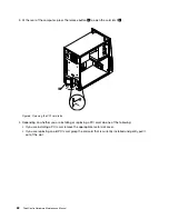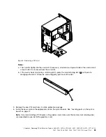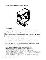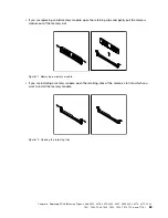
4. Remove any locking device that secures the computer cover, such as a padlock or an integrated
cable lock.
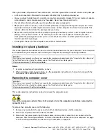
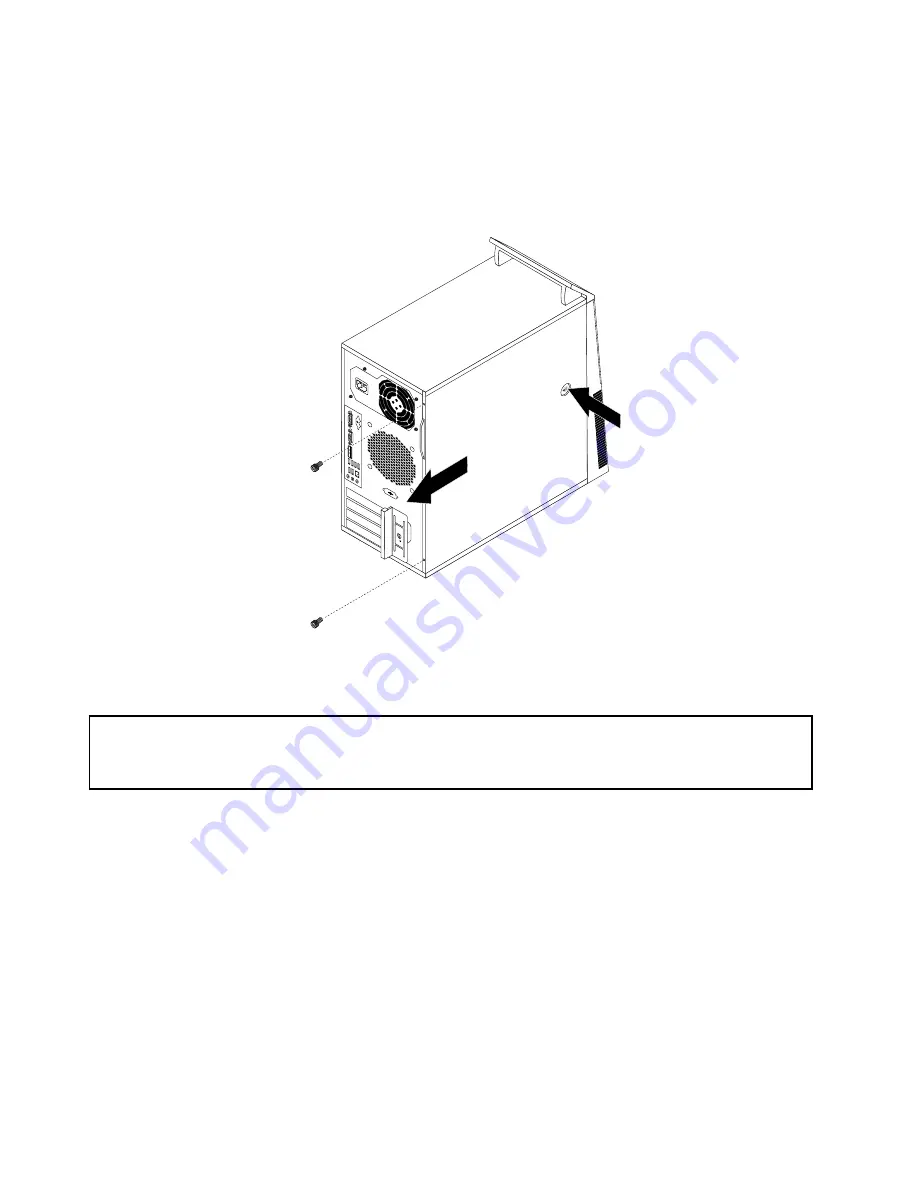
5. Remove any screws that secure the computer cover.
6. Press the cover-release button on the side of the computer and slide the cover to the rear of the
computer to remove the cover.
Figure 6. Removing the computer cover
Removing and reinstalling the front bezel
Attention:
Do not open your computer or attempt any repair before reading and understanding the “Important safety information”
in the
ThinkCentre User Guide
. To obtain a copy of the
ThinkCentre User Guide
, go to:
http://www.lenovo.com/ThinkCentreUserGuides
This section provides instructions on how to remove and reinstall the front bezel.
To remove and reinstall the front bezel, do the following:
1. Turn off the computer and disconnect all power cords from electrical outlets.
2. Remove the computer cover. See “Removing the computer cover” on page 79.
80
ThinkCentre Hardware Maintenance Manual
Summary of Contents for 4513
Page 2: ......
Page 8: ...vi ThinkCentre Hardware Maintenance Manual ...
Page 17: ...Chapter 2 Safety information 9 ...
Page 18: ... 18 kg 37 lbs 32 kg 70 5 lbs 55 kg 121 2 lbs 10 ThinkCentre Hardware Maintenance Manual ...
Page 22: ...14 ThinkCentre Hardware Maintenance Manual ...
Page 23: ...1 2 Chapter 2 Safety information 15 ...
Page 24: ...1 2 16 ThinkCentre Hardware Maintenance Manual ...
Page 30: ...22 ThinkCentre Hardware Maintenance Manual ...
Page 31: ...1 2 Chapter 2 Safety information 23 ...
Page 35: ...Chapter 2 Safety information 27 ...
Page 36: ...1 2 28 ThinkCentre Hardware Maintenance Manual ...
Page 40: ...32 ThinkCentre Hardware Maintenance Manual ...
Page 56: ...48 ThinkCentre Hardware Maintenance Manual ...
Page 80: ...72 ThinkCentre Hardware Maintenance Manual ...
Page 170: ...162 ThinkCentre Hardware Maintenance Manual ...
Page 486: ...478 ThinkCentre Hardware Maintenance Manual ...
Page 491: ......
Page 492: ...Part Number 0A23284 Printed in USA 1P P N 0A23284 0A23284 ...

