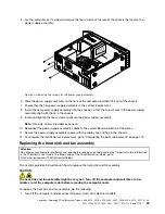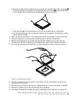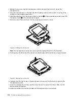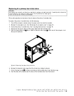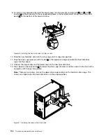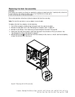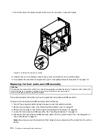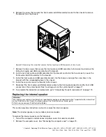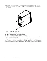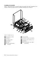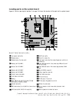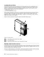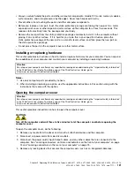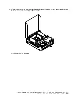
5. The rear fan assembly is attached to the chassis by four rubber mounts. Remove the rear fan assembly
by breaking or cutting the rubber mounts and gently pulling the rear fan assembly out of the chassis.
Note:
The new rear fan assembly will have four new rubber mounts attached.
Figure 43. Removing the rear fan assembly
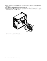
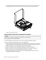
6. Install the new rear fan assembly by aligning the new rubber mounts with the corresponding holes in the
chassis and push the rubber mounts through the holes.
Chapter 8
.
Replacing FRUs (Machine Types: 4468, 4473, 4476, 4479, 4495, 4497, 4499, 4504, 4513, 4517, 4524,
7021, 7032, 7034, 7049, 7052, 7053, 7073, 7136, and 7178.)
109
Summary of Contents for 4513
Page 2: ......
Page 8: ...vi ThinkCentre Hardware Maintenance Manual ...
Page 17: ...Chapter 2 Safety information 9 ...
Page 18: ... 18 kg 37 lbs 32 kg 70 5 lbs 55 kg 121 2 lbs 10 ThinkCentre Hardware Maintenance Manual ...
Page 22: ...14 ThinkCentre Hardware Maintenance Manual ...
Page 23: ...1 2 Chapter 2 Safety information 15 ...
Page 24: ...1 2 16 ThinkCentre Hardware Maintenance Manual ...
Page 30: ...22 ThinkCentre Hardware Maintenance Manual ...
Page 31: ...1 2 Chapter 2 Safety information 23 ...
Page 35: ...Chapter 2 Safety information 27 ...
Page 36: ...1 2 28 ThinkCentre Hardware Maintenance Manual ...
Page 40: ...32 ThinkCentre Hardware Maintenance Manual ...
Page 56: ...48 ThinkCentre Hardware Maintenance Manual ...
Page 80: ...72 ThinkCentre Hardware Maintenance Manual ...
Page 170: ...162 ThinkCentre Hardware Maintenance Manual ...
Page 486: ...478 ThinkCentre Hardware Maintenance Manual ...
Page 491: ......
Page 492: ...Part Number 0A23284 Printed in USA 1P P N 0A23284 0A23284 ...

