2. From the Setup Utility program main menu, select
Security
.
3. Depending on the password type, select
Set Power-On Password
,
Set Administrator Password
, or
Hard Disk Password
.
4. Follow the instructions on the right side of the screen to set, change, or delete a password.
Note:
A password can be any combination of up to 64 alphabetic and numeric characters. For more
information, see “Password considerations” on page 44.
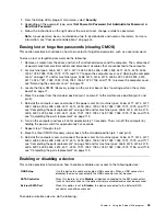
Erasing lost or forgotten passwords (clearing CMOS)
This section provides instructions on how to erase lost or forgotten passwords, such as a user password.
To erase a lost or forgotten password, do the following:
1. Remove all media from the drives and turn off all attached devices and the computer. Then, disconnect
all power cords from electrical outlets and disconnect all cables that are connected to the computer.
2. For machine types: 4466, 4471, 4474, 4477, 4480, 4485, 4496, 4498, 4503, 4512, 4514, 4518, 4554,
7005, 7023, 7033, 7035, 7072, 7079, and 7177, to open the computer cover, see “Opening the computer
cover” on page 121 and for machine types: 4468, 4473, 4476, 4479, 4495, 4497, 4499, 4504, 4513,
4517, 4524, 7021, 7032, 7034, 7049, 7052, 7053, 7073, 7136, and 7178, to remove the computer cover ,
see “Removing the computer cover” on page 79
3. Locate the Clear CMOS /Recovery jumper on the system board. See “Locating parts on the system
board” on page 77.
4. Move the jumper from the standard position (pin 1 and pin 2) to the maintenance position (pin 2 and
pin 3).
5. Reinstall the computer cover and connect the power cord. For machine types: 4466, 4471, 4474, 4477,
4480, 4485, 4496, 4498, 4503, 4512, 4514, 4518, 4554, 7005, 7023, 7033, 7035, 7072, 7079, and 7177,
see “Completing the parts replacement” on page 160 and for machine types: 4468, 4473, 4476, 4479,
4495, 4497, 4499, 4504, 4513, 4517, 4524, 7021, 7032, 7034, 7049, 7052, 7053, 7073, 7136, and 7178,
see “Completing the parts replacement” on page 113
6. Turn on the computer and leave it on for approximately 10 seconds. Then, turn off the computer by
holding the power switch for approximately five seconds.
7. Repeat step 1 through step 2.
8. Move the Clear CMOS /Recovery jumper back to the standard position (pin 1 and pin 2).
9. Reinstall the computer cover and connect the power cord. For machine types: 4466, 4471, 4474, 4477,
4480, 4485, 4496, 4498, 4503, 4512, 4514, 4518, 4554, 7005, 7023, 7033, 7035, 7072, 7079, and 7177,
see “Completing the parts replacement” on page 160 and for machine types: 4468, 4473, 4476, 4479,
4495, 4497, 4499, 4504, 4513, 4517, 4524, 7021, 7032, 7034, 7049, 7052, 7053, 7073, 7136, and 7178,
see “Completing the parts replacement” on page 113
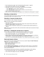
Enabling or disabling a device
This section provides information on how to enable or disable user access to the following devices:
USB Setup
Use this option to enable or disable a USB connector. When a USB connector is
disabled, the device connected to the USB connector cannot be used.
SATA Controller
When this feature is set to
Disable
, all devices connected to the SATA connectors
(such as hard disk drives or the optical drive) are disabled and cannot be accessed.
External SATA Port
When this option is set to
Disable
, the device connected to the External SATA
connector cannot be accessed.
To enable or disable a device, do the following:
Chapter 6
.
Using the Setup Utility program
45
Summary of Contents for 4513
Page 2: ......
Page 8: ...vi ThinkCentre Hardware Maintenance Manual ...
Page 17: ...Chapter 2 Safety information 9 ...
Page 18: ... 18 kg 37 lbs 32 kg 70 5 lbs 55 kg 121 2 lbs 10 ThinkCentre Hardware Maintenance Manual ...
Page 22: ...14 ThinkCentre Hardware Maintenance Manual ...
Page 23: ...1 2 Chapter 2 Safety information 15 ...
Page 24: ...1 2 16 ThinkCentre Hardware Maintenance Manual ...
Page 30: ...22 ThinkCentre Hardware Maintenance Manual ...
Page 31: ...1 2 Chapter 2 Safety information 23 ...
Page 35: ...Chapter 2 Safety information 27 ...
Page 36: ...1 2 28 ThinkCentre Hardware Maintenance Manual ...
Page 40: ...32 ThinkCentre Hardware Maintenance Manual ...
Page 56: ...48 ThinkCentre Hardware Maintenance Manual ...
Page 80: ...72 ThinkCentre Hardware Maintenance Manual ...
Page 170: ...162 ThinkCentre Hardware Maintenance Manual ...
Page 486: ...478 ThinkCentre Hardware Maintenance Manual ...
Page 491: ......
Page 492: ...Part Number 0A23284 Printed in USA 1P P N 0A23284 0A23284 ...

