


Step 4.
Remove the two screws that secure the computer cover at the rear of the chassis.
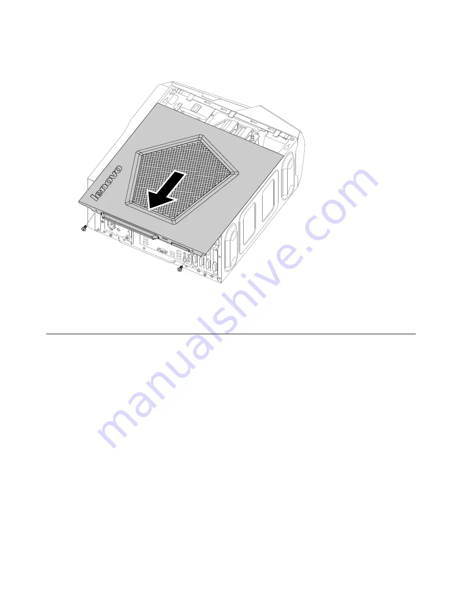
Step 5.
Slide the computer cover out to remove it.
Step 6.
To reattach the computer cover:
a.
Line up the computer cover with the chassis and slide it back into position.
b.
Secure the computer cover to the chassis with the two screws.
Replacing a memory module
Note:
For this procedure, it helps to lay the computer flat.
To replace an optical drive:
Step 1.
Remove any media (disks, CDs, DVDs, or memory cards) from the drives, shut down the operating
system, and turn off the computer and all attached devices.
Step 2.
Unplug all power cords from electrical outlets.
Step 3.
Disconnect all cables attached to the computer. This includes power cords, input/output (I/O)
cables, and any other cables that are connected to the computer. Refer to “Left and right view”
and “Rear view” for help with locating the various connectors.
Step 4.
Remove the computer cover. Refer to “Removing the computer cover”.
Step 5.
Locate the memory module connectors. Refer to “Locating components”.
28
Lenovo Erazer X510Hardware Maintenance Manual
Summary of Contents for 10140/90AC
Page 2: ......
Page 3: ...Lenovo Erazer X510 Hardware Maintenance Manual Machine Types 10140 90AC 10143 90AD ...
Page 6: ...iv Lenovo Erazer X510Hardware Maintenance Manual ...
Page 8: ...2 Lenovo Erazer X510Hardware Maintenance Manual ...
Page 16: ...10 Lenovo Erazer X510Hardware Maintenance Manual ...
Page 18: ...12 Lenovo Erazer X510Hardware Maintenance Manual ...
Page 24: ...18 Lenovo Erazer X510Hardware Maintenance Manual ...
Page 51: ...Step 6 Disconnect the power cable from the power board 1 Chapter 8 Replacing hardware 45 ...