


16
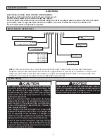
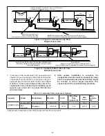
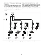
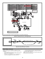
Figure 17. Typical Communication Wiring Diagram (VRF Heat Pump System)
(PQ)
(PQ)
Outdoor unit
(main unit)
Outdoor unit
(sub1 unit)
Outdoor unit
(sub2 unit)
Install a terminating resistor (Ω120) at the last indoor unit terminals
P
and Q of the daisy chain.
P Q
All shields
of
shielded
cable
connect
to
chassis
GROUND
terminal at Indoor Units.
18 GA
.,
stranded,
2-conducto
r
,
shielded
control
wire (polarit
y
sensitiv
e).
T
ypical Wiring Diagram, NEC/CEC and Local Codes apply.
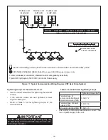
(H1 H2 )
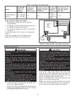
Outdoor Unit Communication Terminal Block
P
Q
H1 H2
X
Y
O
A
K1 K2
(H1 H2 )
(H1 H2 )
Indoor Unit Communication Terminal Block
HA HB 12V COM P
Q
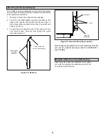
Ground
c
able s
hield
to Indoor Unit chassis
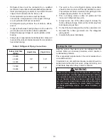
Tightening torque for the terminal screws
• Use the correct screwdriver for tightening the terminal
screws.
• If the terminal screws are over tightened, screws
might be damaged.
• Refer to Table 5 for the tightening torque of the
terminal screws.
Table 5. Terminal Screw Tightening Torque
Tightening torque (lb-ft)
Terminal base of
remote controller/Signal
transmission wire (X2M)
0.58-0.72
Terminal base of power
supply (X1M)
0.87-1.06
Grounding terminal (M4)
1.06-1.43
•
After wiring, confirm all connections are correct; Then
turn on power supply to the unit.
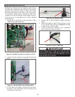
IMPORTANT
DO NOT adjust DIP switch settings. Settings may only
be adjusted by a trained technician as part of the com-
missioning procedures.