


Page 58
VI-TYPICAL OPERATING CHARACTERISTICS
A-Blower Operation and Adjustment
1 - Blower operation is dependent on thermostat control
system.
2 - Generally, blower operation is set at thermostat subbase
fan switch. With fan switch in ON position, blower oper
ates continuously. With fan switch in AUTO position,
blower cycles with demand or runs continuously while
heating or cooling circuit cycles.
3 - Depending on the type of indoor thermostat, blower and
entire unit will be off when the system switch is in OFF
position.
B-Temperature Rise
Temperature rise for SLP98DFV units depends on unit in
put, blower speed, blower horsepower and static pressure
as marked on the unit rating plate. The blower speed must
be set for unit operation within the range of “TEMP. RISE
°
F” listed on the unit rating plate.
To Measure Temperature Rise:
1 - Place plenum thermometers in the supply and return air
plenums. Locate supply air thermometer in the first hori
zontal run of the plenum where it will not pick up radiant
heat from the heat exchanger.
2 - Set thermostat for heat call. Unit must operate on sec
ond-stage heat.
If using a single-stage thermostat fur
nace must fire at least 10 minutes before switching to
second-stage heat.
3 - After plenum thermometers have reached their highest
and steadiest readings, subtract the two readings. The
difference should be in the range listed on the unit rating
plate. If the temperature is too low, decrease blower
speed. If temperature is too high, first check the firing
rate. Provided the firing rate is acceptable, increase
blower speed to reduce temperature.
C-External Static Pressure
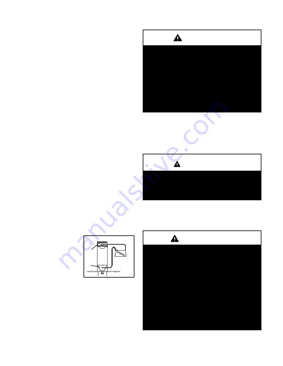
1 - Tap locations shown in figure 50.
2 - Punch a 1/4” diameter hole in
supply and return air ple
nums. Insert manometer
hose flush with inside edge of
hole or insulation. Seal
around the hose with perma
gum. Connect the zero end of
the manometer to the dis
charge (supply) side of the system. On ducted systems,
connect the other end of manometer to the return duct
as above.
3 - With only the blower motor running and the evaporator
coil dry, observe the manometer reading. Adjust blower
motor speed to deliver the air desired according to the
job requirements.
4 - External static pressure drop must not be more than
0.8” W.C. in the heating mode and must not exceed 1.0”
W.C in the cooling mode.
5 - Seal the hole when the check is complete.
VII-MAINTENANCE
WARNING
ELECTRICAL SHOCK, FIRE,
OR EXPLOSION HAZARD.
Failure to follow safety warnings exactly could result
in dangerous operation, serious injury, death or prop
erty damage.
Improper servicing could result in dangerous opera
tion, serious injury, death, or property damage.
Before servicing, disconnect all electrical power to
furnace.
When servicing controls, label all wires prior to dis
connecting. Take care to reconnect wires correctly.
Verify proper operation after servicing.
At the beginning of each heating season, system should be
checked as follows by a qualified service technician:
Blower
Check the blower wheel for debris and clean if necessary.
The blower motors are prelubricated for extended bearing
life. No further lubrication is needed.
WARNING
The blower access panel must be securely in place
when the blower and burners are operating. Gas
fumes, which could contain carbon monoxide, can be
drawn into living space resulting in personal injury or
death.
Filters
All SLP98DFV filters are installed external to the unit. Fil
ters should be inspected monthly. Clean or replace the fil
ters when necessary to ensure proper furnace operation.
All SLP98DFV units use a 16 x 25 x1 filter.
IMPORTANT
If a highefficiency filter is being installed as part of
this system to ensure better indoor air quality, the fil
ter must be properly sized. Highefficiency filters
have a higher static pressure drop than standardeffi
ciency glass/foam filters. If the pressure drop is too
great, system capacity and performance may be re
duced. The pressure drop may also cause the limit to
trip more frequently during the winter and the indoor
coil to freeze in the summer, resulting in an increase
in the number of service calls.
Before using any filter with this system, check the
specifications provided by the filter manufacturer
against the data given in the appropriate Lennox
Product Specifications bulletin. Additional informa
tion is provided in Service and Application Note
ACC002 (August 2000).
Exhaust and air intake pipes
Check the exhaust and air intake pipes and all connections
for tightness and to make sure there is no blockage.
STATIC PRESSURE TEST
filter
coil


