


Page 30
8. Combustion Air Inducer (B6) & Pressure Switch
(S18)
All SLP98DFV units are equipped with a combustion air in
ducer (B6) and
dual
pressure switch assembly (high fire and
low fire). The pressure switch (figure 17) serves four func
tions. First it establishes calibration points for the vent cal
ibration routine. The combustion air inducer's speed at a giv
en firing rate is a function of the vent system resistance. The
calibration routine establishes the inducer speed required to
make low and high fire switches for a given vent pipe installa
tion and interpolates the speeds required to achieve all inter
mediate rates between these two points. The setting for low-
fire switch on the assembly is such that it does not normally
enter into the vent calibration routine.
Second, the switch proves combustion air inducer operation
by sensing a vacuum energizing the control circuit and allow
ing ignition. The low fire pressure switch provides this func
tion.
Third, the switch interrupts the combustion process in the
event vent outlet or combustion air intake blockage.
Finally, the switch interrupts the combustion process if the
condensate drainage system becomes blocked to the point
the condensate level builds up in the cold end header box/
secondary coil or vent system.
If the switch assembly is to be replaced, replace the entire
assembly. Individual switch components can not be re
placed.
WARNING
The pressure switch is a safety shut-down control in
the furnace and must not be jumpered for any rea
son other than troubleshooting.
To troubleshoot the pressure switch, add a temporary jumper.
The unit will not fire with the switch jumpered. Therefore, the
pressure switch must be bypassed after the combustion air in
ducer is activated. This will determine if the pressure switch
and furnace are operating properly. However, this may not indi
cate if the sealed combustion system is operating properly.
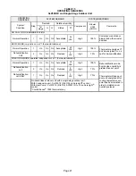
FIGURE 17
bracket
low fire
high fire
Pressure Switch (S18)
Vent Calibration
The vent calibration sequence establishes furnace operat
ing parameters in a specific installation. The integrated con
trol runs the calibration and may be repeated as necessary
to maintain proper furnace operation. Prior to calibration, all
duct work (and returns) vent pipe and condensate trap
(primed) must be connected.
If calibration is successful the data is stored in memory and
will be used to determine furnace operation and maintain
parameters during heat call. If calibration is not successful,
the integrated control will proceed to a 5 minute delay and
signal the appropriate code. After the 5 minute delay the cal
ibration will be repeated 4 more times with a 5 minute delay
in between. If still unsuccessful after the 4 trials (total 5) the
integrated control will go into a 1 hour soft lockout.
Calibration may be initiated by:
S
Initial call for heat
S
Cycling main power off / on and then call for heat
S
Venting conditions change (affecting high and low
pressure switch operation)
S
Ramp down low fire switch check failed (calibration
will follow next call for heat)
S
The service technician (by pressing the push button
found on the integrated control until the control cycles
through to “Field Test Mode”)
The integrated control will do the following during
calibration:
1- Verify both low pressure switch and high pressure
switch are open. If either are closed log error and end
calibration.
2- Start inducer at a predetermined low RPM (1600).
Wait 7.5 seconds.
3- Check low pressure switch, if open, increase RPM by
250, wait 5 seconds. Repeat this step until low pressure
switch is closed.
4- Decrease RPM by 50, wait 5 seconds and look for the
low pressure switch to open. Repeat this step until it is
open.
5- Keep this RPM as RPM1.
6- Increase RPM by 1250. Wait 5 seconds.
7- Check high pressure switch, if open, increase RPM
by 250, wait 5 seconds. Repeat this step until high pres
sure switch is closed.
8- Decrease RPM by 50, check after 5 seconds. Repeat
this step until switch is open.
9- Keep this RPM as RPM2.
10- Calibration complete.
NOTE -
If after a successful calibration and a heat call is
present the integrated control will by-pass the prepurge
state and go straight into ignitor warm up.


