


Page 42
6 - Disconnect wires from flame roll-out switches.
7 - Loosen clamps at vent elbow. Disconnect condensate
drain tubing from flue collar. and remove the vent el
bow.
8 - Remove four burner box screws at the vestibule panel
and remove burner box. Set burner box assembly
aside.
NOTE
- If necessary, clean burners at this time. Follow
procedures outlined in Burner Cleaning section.
9 - Mark and disconnect all combustion air pressure tub
ing from cold end header collector box.
10 - Mark and remove wires from pressure switches. Re
move pressure switches. Keep tubing attached to
pressure switches.
11 - Disconnect the plug from the combustion air inducer.
Remove two screws which secure combustion air in
ducer to collector box. Remove combustion air induc
er assembly. Remove ground wire from vest panel.
12 - Remove electrical junction box from the side of the fur
nace.
13 - Mark and disconnect any remaining wiring to heating
compartment components. Disengage strain relief
bushing and pull wiring and bushing through the hole
in the blower deck.
14 - Remove the primary limit from the vestibule panel.
15 - Remove two screws from the front cabinet flange at
the blower deck. Spread cabinet sides slightly to allow
clearance for removal of heat exchanger.
16 - Remove screws along vestibule sides and bottom
which secure vestibule panel and heat exchanger as
sembly to cabinet. Remove two screws from blower
rail which secure bottom heat exchanger flange. Re
move heat exchanger from furnace cabinet.
17 - Back wash heat exchanger with soapy water solution
or steam.
If steam is used it must be below 275°F
(135°C) .
18 - Thoroughly rinse and drain the heat exchanger. Soap
solutions can be corrosive. Take care to rinse entire
assembly.
19 - Reinstall heat exchanger into cabinet making sure that
the clamshells of the heat exchanger assembly are
resting on the support located at the rear of the cabi
net. Remove the indoor blower to view this area
through the blower opening.
20 - Re‐secure the supporting screws along the vestibule
sides and bottom to the cabinet. Reinstall blower and
mounting screws.
21 - Reinstall cabinet screws on front flange at blower
deck.
22 - Reinstall the primary limit on the vestibule panel.
23 - Route heating component wiring through hole in blow
er deck and reinsert strain relief bushing.
24 - Reinstall electrical junction box.
25 - Reinstall the combustion air inducer. Reconnect the
combustion air inducer to the wire harness.
26 - Reinstall pressure switches and reconnect pressure
switch wiring.
27 - Carefully connect combustion air pressure switch hos
ing from pressure switches to proper stubs on cold end
header collector box.
28 - Reinstall condensate trap.
29 - Reconnect exhaust piping and exhaust drain tubing.
30 - Reinstall burner box assembly in vestibule area.
31 - Reconnect flame roll-out switch wires.
32 - Reconnect sensor wire and reconnect 2-pin plug from
ignitor.
33 - Secure burner box assembly to vestibule panel using
four existing screws.
Make sure burners line up in
center of burner ports.
34 - Reinstall gas valve manifold assembly. Reconnect
gas supply line to gas valve.
35 - Reconnect 2 wires to gas valve.
36 - Replace the blower compartment access panel.
37 - Refer to instruction on verifying gas and electrical con
nections when re-establishing supplies.
38 - Follow lighting instructions to light and operate fur
nace for 5 minutes to ensure that heat exchanger is
clean and dry and that furnace is operating properly.
39 - Replace heating compartment access panel.
Cleaning the Burner Assembly
1 - Turn off electrical and gas power supplies to furnace.
Remove upper and lower furnace access panels.
2 - Disconnect the 2-pin plug from the gas valve.
3 - Remove the burner box cover.
4 - Disconnect the gas supply line from the gas valve. Re
move gas valve/manifold assembly.
5 - Mark and disconnect sensor wire from the sensor. Dis
connect 2‐pin plug from the ignitor at the burner box.
6 - Remove four screws which secure burner box assem
bly to vest panel. Remove burner box from the unit.
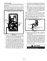
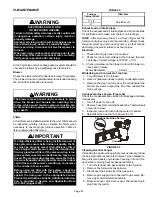
7 - Use the soft brush attachment on a vacuum cleaner to
gently clean the face of the burners. Visually inspect
the inside of the burners and crossovers for any block
age caused by foreign matter. Remove any blockage.
8 - Reconnect the sensor wire and reconnect the 2-pin
plug to the ignitor wiring harness.
9 - Reinstall the burner box assembly using the existing
four screws. Make sure that the burners line up in the
center of the burner ports.
10 - Reinstall the gas valve manifold assembly. Reconnect
the gas supply line to the gas valve. Reinstall the burn
er box cover.
11 - Reconnect 2-pin plug to gas valve.
12 - Replace the blower compartment access panel.
13 - Refer to instruction on verifying gas and electrical con
nections when re-establishing supplies.
14 - Follow lighting instructions to light and operate fur
nace for 5 minutes to ensure that heat exchanger is
clean and dry and that furnace is operating properly.
15 - Replace heating compartment access panel.


