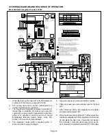
Lennox ML193DF045P36B Unit Information Download Page 39

Page 39

F- Proper Gas Flow (Approximate)

Gas Flow (Approximate)

TABLE 18

GAS METER CLOCKING CHART

ML193

Unit

Seconds for One Revolution

Natural

LP

1 cu ft

Dial

2 cu ft

Dial

1 cu ft

Dial

2 cu ft

DIAL

-045

80

160

200

400

-070

55

110

136

272

-090

41

82

102

204

-110

33

66

82

164


Natural-1000 btu/cu ft              LP-2500 btu/cu ft
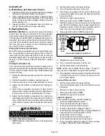
NOTE 

- To obtain accurate reading, shut off all other gas

appliances connected to meter.

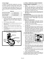
Furnace should operate at least 5 minutes before checking
gas flow. Determine time in seconds for 

two

 revolutions of

gas through the meter. (Two revolutions assures a more
accurate time). 

Divide by two

 and compare to time in table

18. If manifold pressure matches table 19 and rate is incor­
rect, check gas orifices for proper size and restriction. Re­
move temporary gas meter if installed.

TABLE 19

Manifold and Supply Pressure  (Outlet) inches w.c.

At All Altitudes For -1 Through -6 Units

Fuel

Model

Input Sizes

Manifold

Pressure in.wg.

Supply

Pressure in.wg.

Min.

Max.

Nat. Gas

All sizes

3.5

4.5

13.0

L.P. Gas

All sizes

10.0

11.0

13.0

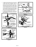
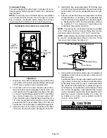
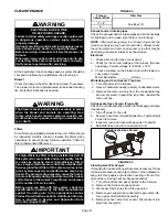
G- Proper Combustion

Furnace should operate at least 15 minutes with correct
manifold pressure and gas flow rate before checking com­
bustions. Take sample beyond the flue outlet and compare
to table 20.

TABLE 20

ML193

Unit

CO

2

%

 For Nat

CO

2

For L.P.

-045

7.2 - 7.9

8.6 - 9.3

-070
-090
-110

The carbon monoxide reading should not exceed 50 ppm.
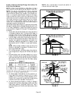
H- High Altitude

NOTE 

- In Canada, certification for installations at eleva­

tions over 4500 feet (1372 m) is the jurisdiction of local au­
thorities.

ML193DF-1 through -6 units require no manifold pressure
adjustments for operation at altitudes up to 10,000 feet
(3048 m) above sea level. However, -7 units and later in­
stalled at altitude of 4501 - 10,000 feet (1373 to 3048m) re­
quire a pressure switch change which can be ordered sep­
arately and manifold de-rate. See table 19 or table 21 for
manifold pressures at varying altitudes. Table 22 lists con­
version kit and pressure switch requirements at varying al­
titudes.
The combustion air pressure switch is factory-set and re­
quires no adjustment.

TABLE 21

Manifold and Supply Line Pressure 0-10,000ft. For -7 Units and Later

ML193

Unit

Gas

Manifold Pressure in. wg.

Supply Line

Pressure

in. w.g.

0 - 10000 ft.

0-4500 ft.

4501-5500 ft.

5501-6500 ft.

6501 -

7500ft.

7501 - 10000ft.

All Sizes

Natural

3.5

3.3

3.2

3.1

3.5

4.5

13.0

LP/propane

10.0

9.4

9.1

8.9

10.0

11.0

13.0

NOTE -


A natural to L.P. propane gas changeover kit is necessary to convert this unit. Refer to the changeover kit installation instruction for the conversion

procedure.

TABLE 22

Conversion Kit and Pressure Switch Requirements at Varying Altitudes

ML193

Unit

Natural to

LP/Propane

High Altitude

Natural Burner Ori­

fice Kit

LP/Propane to

Natural

High Altitude Pressure Switch

0 - 7500 ft

(0 - 2286m)

7501 - 10,000 ft

(2286 - 3038m)

0 - 7500 ft

(0 - 2286m)

4501 - 7500 ft

(1373 - 2286m)

7501 -10,000 ft

(2286 - 3048m)

-045

*69W73

73W37

*73W81

93W87

93W88

-070

-090

-110

* Conversion requires installation of a gas valve manifold spring which is provided with the gas conversion kit.
Pressure switch is factory set. No adjustment necessary. All models use the factory-installed pressure switch from 0-4500 feet (0-1370 m).

Summary of Contents for ML193DF045P36B

Page 1: ...detailed description on how this is done All specifications are subject to change Procedures out lined in this manual are presented as a recommendation only and do not supersede or replace local or st...

Page 2: ...d 1 2 1 2 1 2 1 2 with field supplied PVC coupling o d 3 4 3 4 3 4 3 4 Indoor Blower Wheel nom dia x width in 10 x 8 10 x 8 10 x 10 11 x 10 Motor output hp 1 3 1 3 1 2 1 Tons of add on cooling 2 5 3 2...

Page 3: ...oncentric US 2 in 71M80 69M29 3 in 60L46 Canada 2 in 44W92 44W92 3 in 44W93 Flush Mount 2 2 1 2 or 3 in 51W11 51W11 Wall Close Couple US 2 in 22G44 3 in 44J40 44J40 Wall Close Couple WTK Canada 2 in 3...

Page 4: ...165 1610 850 1495 720 1370 615 0 80 1625 1155 1510 820 1400 695 1315 595 0 90 1455 1110 1390 790 1350 660 1210 565 ML193DF045XP36B PERFORMANCE Less Filter External Static Pressure in w g Air Volume Wa...

Page 5: ...and door switch BAG ASSEMBLY BLOWER MOTOR hidden BLOWER ACCESS PANEL BURNER ACCESS PANEL COMBUSTION AIR INDUCER BURNER BOX ASSEMBLY includes sensor rollout switches and ignitor GAS VALVE BLOWER DECK...

Page 6: ...ignition control system consists of an integrated con trol figure 4 ignitor figure 10 and sensor figure 10 The integrated control and ignitor work in combination to en sure furnace ignition and ignit...

Page 7: ...tage conditions Fan Control The fan on time of 30 seconds is not adjustable The fan off delay amount of time that the blower operates after the heat demand has been satisfied may be adjusted by changi...

Page 8: ...lame 5 times during single heating demand SLOW FLASH OFF Flame sensed without gas valve energized ON SLOW FLASH Rollout switch open OR 12 pin connector improperly attached ON ON OFF ON OFF ON Circuit...

Page 9: ...he trial for ignition If ignition is not proved during the trial for ignition the integrated control will try four more times with an inter purge and warm up time between trials of 30 seconds After a...

Page 10: ...g Speed 120VAC Blower Heating Speed 120VAC Dead terminals to park alternate spd taps Continuous blower Neutral terminals 120VAC PUSH BUTTON LED TWIN TWIN Twinning Terminal 24VAC DEMAND CAI GAS VALVE 1...

Page 11: ...NO JUMPER FIGURE 8 60 90 120 180 60 90 120 180 60 90 120 180 60 90 120 180 60 Second off Time 90 Second off Time 120 Second off Time 180 Second off Time Twinning 2 ML193DF Furnaces Integrated control...

Page 12: ...TWO STAGE THERMOSTAT Call For Cool Call For Fan Call For 1st Stage Heat Call For 2nd StageHeat R Y G W1 W2 Y W C Y W R R G C G TWIN TWIN TWIN 2 TWIN 1 ISOLATION RELAY Call For Cool Call For Fan Call F...

Page 13: ...The sensor can be removed for service with out removing any part of the burners During operation flame is sensed by current passed through the flame and sensing electrode The ignition control allows...

Page 14: ...lem is with the wiring between the jack plug and the control If reading is not correct the issue is the ignitor Test 3 Check ignitor for correct voltage Insert meter probes into terminals 2 and 4 use...

Page 15: ...ngers and exhausted out the exhaust vent pipe 6 Burners Figure 13 All units use inshot burners Burners are factory set and do not require adjustment Burners can be removed as an as sembly for service...

Page 16: ...he CAI orifice to insure proper flow through the heat exchanger The switch is a SPST N O prove switch electrically con nected to the integrated control The purpose of the switch is to prevent burner o...

Page 17: ...the pressure differential The pressure differential should be greater than those listed in table 10 5 Remove thermostat demand and allow to cycle off 6 Remove manometer and tee s Reinstall combustion...

Page 18: ...TM SPECIFICATION PVC CPVC Primer F656 PVC Solvent Cement D2564 CPVC Solvent Cement F493 ABS Solvent Cement D2235 PVC CPVC ABS All Purpose Cement For Fittings Pipe of the same material D2564 D2235 F493...

Page 19: ...S 110 2 YES YES YES 5YES YES YES 2 1 2 YES YES 5YES YES YES 3 YES YES 5YES YES YES NOTE Standard Terminations do not include any vent pipe or elbows external to the structure Any vent pipe or elbows e...

Page 20: ...e and end of pipe are wet with cement forcefully insert end of pipe into socket until it bottoms out Turn PVC pipe 1 4 turn dur ing assembly but not after pipe is fully inserted to dis tribute cement...

Page 21: ...restrict ive The PolyPro by Duravent venting system must also fol low the uninsulated and unconditioned space criteria listed in table 16 The ML193DF can be installed as either a Non Direct Vent or a...

Page 22: ...lbows inside and outside the house What is the altitude of the furnace installation 7 What is the furnace capacity 045 070 090 or 110 NOTE It is acceptable to use any pipe size which fits within the g...

Page 23: ...pe 3 Pipe Model Model Model 045 070 090 110 045 070 090 110 045 070 090 110 1 53 38 22 n a 90 70 39 n a 111 111 104 104 2 48 33 17 85 65 34 106 106 99 99 3 43 28 12 80 60 29 101 101 94 94 4 38 23 n a...

Page 24: ...st length of 2 PVC pipe possible NOTE Intake pipe and exhaust pipe must be the same diameter 2 2 2 Intake Piping The ML193DF furnace may be installed in either direct vent or non direct vent applicati...

Page 25: ...e maximum volume of combustion air required for all gas appliances serviced by this space FIGURE 24 EQUIPMENT IN CONFINED SPACE Inlet Air from Ventilated Attic and Outlet Air to Outside NOTE The inlet...

Page 26: ...nal B149 installation codes the minimum allowed distance between the combustion air intake inlet and the exhaust outlet of other appliances shall not be less than 12 inches 305mm TABLE 16 Maximum Allo...

Page 27: ...y inlet Clearance above paved sidewalk or paved driveway located on public property Clearance under veranda porch deck or balcony 12 Equal to or greater than soffit depth 3 feet 9m 12 3 feet 9m within...

Page 28: ...ve paved sidewalk or paved driveway located on public property Clearance under veranda porch deck or balcony 12 7 feet 2 1m 3 feet 9m within a height 15 feet 4 5m above the meter regulator assembly 3...

Page 29: ...3 On roof terminations the intake piping should termi nate straight down using two 90 elbows See figure 31 4 Exhaust piping must terminate straight out or up as shown A reducer may be required on the...

Page 30: ...d CLAMP FIELD PROVIDED REDUCER MAY BE REQUIRED TO ADAPT LARGER VENT PIPE SIZE TO TERMINATION INTAKE 1 1 2 38mm accelerator provided on 71M80 44W92 kits for ML193DF045P36B 070P36B 12 305mm 12 305mm Min...

Page 31: ...227 mm Min 12 305 mm Min 16 405 mm Max 6 152 mm Max 6 152 mm Min 24 610 mm Max 9 227 mm Min 12 305 mm Min 20 508 mm Max 6 152 mm Max Intake Elbow WALL SUPPORT B A D E B D E A ALTERNATE TERMINATIONS TE...

Page 32: ...the building FIGURE 38 NON DIRECT VENT ROOF TERMINATION KIT 15F75 or 44J41 UNCONDITIONED ATTIC SPACE 3 76mm OR 2 51mm PVC PROVIDE SUPPORT FOR EXHAUST LINES 12 305mm ABOVE AVE SNOW ACCUMULATION SIZE T...

Page 33: ...nts Glue the provided drain trap as shown in fig ures 46 and 47 Route the condensate line to an open drain 5 Figure 44 shows the furnace and evaporator coil using a separate drain If necessary the con...

Page 34: ...eld Provided Vent 1 min 2 max above condensate drain FIGURE 44 ML193DF with Evaporator Coil Using a Separate Drain Drain Field Provided Vent 1 min 2 max above condensate drain Condensate Drain Connect...

Page 35: ...Condensate Drain Connection In Unit Vent To Drain Condensate Drain Connection In Unit Optional Condensate Drain Connection OptionalDrainPipingFromTrap DrainTrapAssembly Furnished DrainTrap Assembly w...

Page 36: ...inch PVC Not Furnished 1 2 inch PVC Pipe Not Furnished Drain Assembly for 3 4 inch Drain Pipe 90 Street Elbow 1 2 inch PVC Not Furnished Condensate Drain Connection In Unit Adapter 1 2 inch slip X 1 2...

Page 37: ...p should be primed with suffi cient water to ensure proper condensate drain opera tion WARNING If you do not follow these instructions exactly a fire or explosion may result causing property damage pe...

Page 38: ...er 31B2001 See Corp 8411 L10 for further details WARNING Do not use matches candles flame or any other source of ignition to check for gas leaks D Testing Gas Supply Pressure When testing supply gas p...

Page 39: ...risdiction of local au thorities ML193DF 1 through 6 units require no manifold pressure adjustments for operation at altitudes up to 10 000 feet 3048 m above sea level However 7 units and later in sta...

Page 40: ...switch is in OFF position B Temperature Rise Temperature rise depends on unit input blower speed blower horsepower and static pressure as marked on the unit rating plate The blower speed must be set...

Page 41: ...d by the filter manufacturer against the data given in the appropriate Lennox Product Specifications bulletin Additional informa tion is provided in Service and Application Note ACC 00 2 August 2000 T...

Page 42: ...connect the combustion air inducer to the wire harness 26 Reinstall pressure switches and reconnect pressure switch wiring 27 Carefully connect combustion air pressure switch hos ing from pressure swi...

Page 43: ...2 minutes or control goes into 5 minute Watchguard Pressure Switch delay Once S18 closes a 15 second pre purge follows 4 The integrated control A92 energizes ignitor A 20 second warm up period begins...

Page 44: ...MUM OF 1 SECOND GAS VALVE OFF COMBUSTION AIR INDUCER ON INDOOR BLOWER ON HEATING SPEED LED 1 SLOW FLASH LED 2 OFF GAS VALVE OFF COMBUSTION AIR INDUCER OFF INDOOR BLOWER OFF WITH DELAY LED 1 OFF LED 2...

Page 45: ...PLETE YES 4 SECONDS YES HAS CONTROL RESET IGNITION SEQUENCE FOUR TIMES FLAME SIGNAL 1 5 MICROAMPS OR GREATER YES YES YES ROLLOUT SWITCH CLOSED GAS VALVE POWER OFF COMBUSTION AIR INDUCER POWER ON INDOO...

Page 46: ...ASH RATE REMAINS UNCHANGED THROUGHOUT COOLING CYCLE THERMOSTAT CALLS FOR COOLING COMPRESSOR CONTACTOR AND SYSTEM FAN ENERGIZED WITH 2 SECOND DELAY COOLING SPEED EAC TERM ENERGIZED COMPRESSOR OFF THERM...

Page 47: ...ED THERMOSTAT CALLS FOR HEAT W THERMOSTAT CALLS FOR COOLING THERMOSTAT OPENS SYSTEM FAN SWITCHED TO COOL SPEED EAC TERM REMAINS ON THERMOSTAT OPENS MANUAL FAN SELECTION MADE AT THERMOSTAT CONTROL G EN...

Page 48: ...oes into 5 minute Watchguard Pressure Switch delay Once S18 closes a 15 second pre purge follows 4 The integrated control A92 energizes ignitor A 20 second warm up period begins 5 Gas valve opens for...

Page 49: ...DOOR BLOWER ON HEATING SPEED LED 1 FLASH GAS VALVE OFF COMBUSTION AIR INDUCER OFF INDOOR BLOWER OFF WITH DELAY LED 2 FLASHES Sequence holds until pressure switch opens or thermostat resets control NO...

Page 50: ...HEAT DEMAND WATCHGUARD MODE GAS VALVE OFF COMBUSTION AIR INDUCER OFF INDOOR BLOWER OFF WITH DELAY LED 7 FLASHES WATCHGUARD FAILURE CODE IS 60 MINUTE RESET PERIOD COMPLETE NO 4 SECONDS YES HAS CONTROL...

Page 51: ...AC TERM OFF WITH 60 SECOND DELAY NO NO IS VOLTAGE ABOVE 90 VOLTS LED ON STEADY CONTROL WILL CONTINUE TO CALL FOR COOLING IN THIS CONDITION YES NO IS THERE A PROPER GROUND YES NO LED ON STEADY CONTROL...

Reviews: